

Continuously variable valve actuation apparatus for an internal combustion engine
a technology of valve actuator and internal combustion engine, which is applied in the direction of valve arrangement, mechanical equipment, machines/engines, etc., can solve the problems of higher requirements for machining accuracy, higher production cost, and system sensitive to component dimensional errors, etc., and achieves low friction, low inertia, and simple and robust
- Summary
- Abstract
- Description
- Claims
- Application Information
AI Technical Summary
Benefits of technology
Problems solved by technology
Method used
Image

Examples
first embodiment
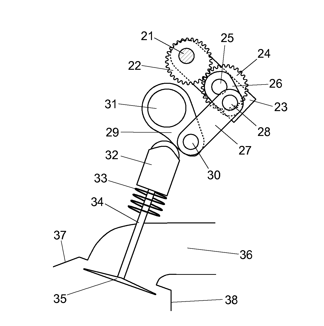
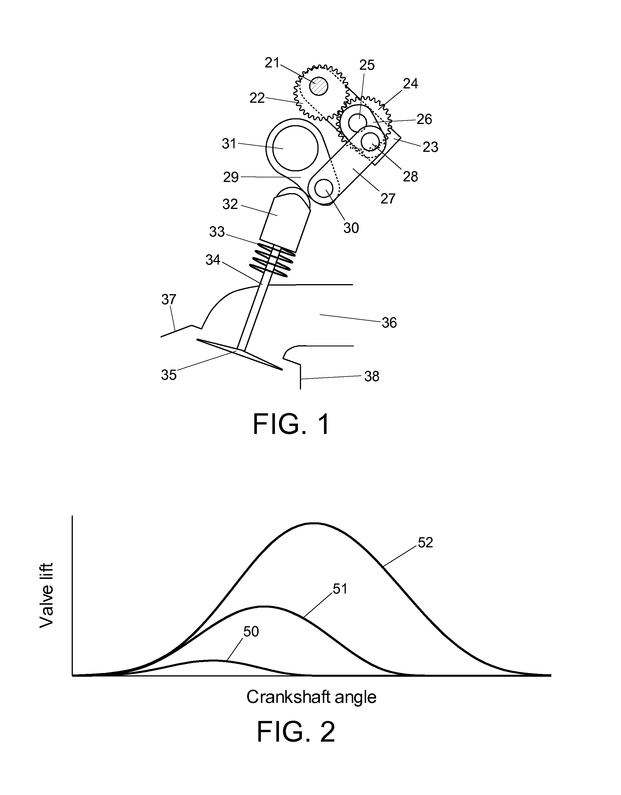
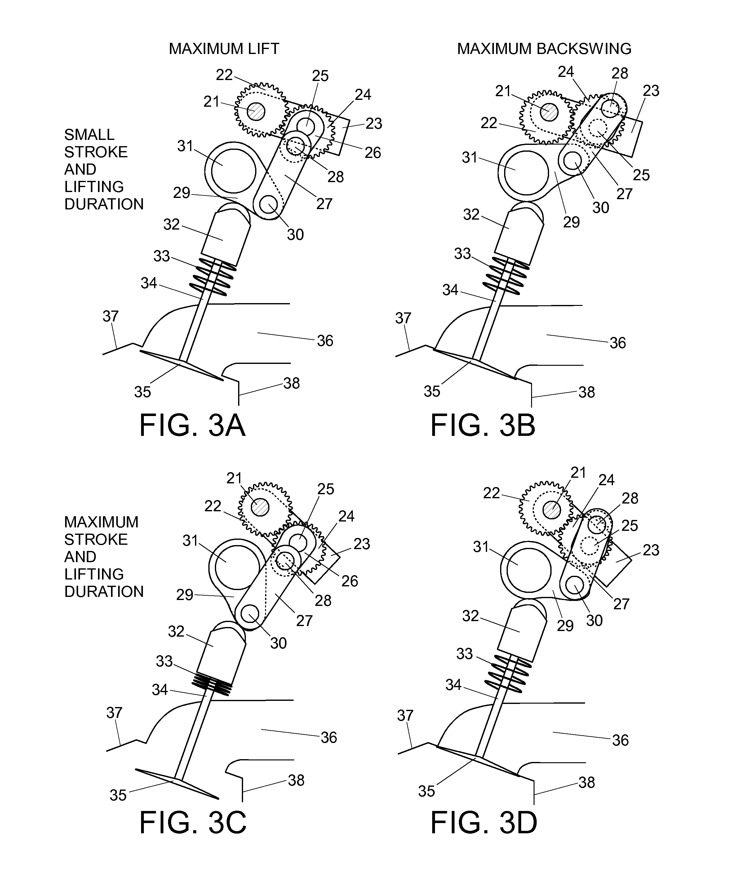
[0044]Gear wheels 22 and 24 of the first embodiment are elliptical and rotate about an elliptical focus. This is an example of an optimized gear wheel geometry. Some advantages of gear wheels with optimized geometries will be discussed later.
[0045]FIG. 2 shows three valve lift curves: a curve with small stroke 50, a curve with intermediate stroke 51, and a curve with maximum stroke 52. These three lift curves are sampled from the continuous spectrum of lift curves that can be generated by the first embodiment. It is also possible to reduce the stroke to zero. Stroke and lifting duration are coupled with phasing, such that timing of valve opening is approximately constant, and timing of valve closing is retarded, as stroke and lifting duration are increased. This can be advantageous for intake valves in spark ignition engines, where stroke and lifting duration are varied to control the charge filling instead of using a throttle valve, as this coupling of stroke and lifting duration w...
seventh embodiment
[0064]FIG. 16A shows a seventh embodiment, where valve lash adjustment is provided by a movable support for fulcrum 31 of rocker cam assembly 29. Fulcrum 31 is supported by a lever 44, and a fulcrum 45 of lever 44 is supported by the engine head. A hydraulic valve lash adjuster 46 controls the angular position of lever 44. Hence, valve lash adjustment is provided without adding inertia to the valve train. A control linkage 60 for controlling the angular position of frame 23 is also shown. A control shaft 61 is rotated by a servo mechanism (not shown). A control arm 62 is attached to control shaft 61, and a control rod 63 is pivotally connected to control arm 62 and frame 23. FIG. 16B shows the same view, but frame 23 and control linkage 60 have been omitted in order to reveal other parts.
[0065]FIG. 17A shows an eighth embodiment having two crank arms 26, two connecting rods 27, and two rocker cam assemblies 29. Hence, this embodiment actuates two valves. Valve lash adjustment has be...
tenth embodiment
[0067]FIG. 18A shows an tenth embodiment, where rocker cam assembly 29 provides two cam lobes, each contacting a separate finger follower 47 with a roller. Hence, this embodiment actuates two valves. Valve lash adjustment is implemented with a hydraulic pivot elements 48 for each finger follower 47. FIG. 18B shows the same view, but frame 23 and control linkage 60 have been omitted in order to reveal other parts.
[0068]FIG. 19 shows an eleventh embodiment. This embodiment is essentially a dual implementation of the tenth embodiment, actuating two intake and two exhaust valves. The parts specifically driving the intake valves have the letter A appended to the part numbers, and the parts specifically driving the exhaust valves have the letter B appended to the part numbers. Otherwise, parts are numbered as for the tenth embodiment. The mechanisms for actuating intake and exhaust valves, respectively, share a common driving shaft 21. Two first gear wheels 22A and 22B are attached to dri...
PUM
 Abstract
Description
Claims
Application Information