Method for fabricating a flexible device

Inactive Publication Date: 2012-09-20
ETERNAL MATERIALS CO LTD
View PDF16 Cites 65 Cited by
  • Summary
  • Abstract
  • Description
  • Claims
  • Application Information

AI Technical Summary

Benefits of technology

[0013]The method of the present invention may be conducted by using the existing manufacturing equipments, so as to decrease the cost. In the fabrication process of the device, a flexible substrate can be effectively fixed on a rigid carrier to reduce an alignment deviation resulting from the movement of the flexible substrate in the fabrication pro

Problems solved by technology

The use of this kind of rigid display is limited due to the lack of flexibility.
The fabrication process of a flexible display with a thin glass substrate is similar to that of a rigid FPD produced on a large scale; however, in order to make the substrate flexible, the substrate must be thin enough, thus being fragile and less safe.
In addition, the flexibility of the thin glass substrate is not competitive with other flexible substrates.
The metal foil substrate has the advantages of high-temperature resistance, high moisture and gas barrier properties, and chemical resistance, but suffers from the disadvantage of being non-transparent, and thus can only be adapted to a particular display device, for example, a reflective display.
However, most of the plastic substrates are not resistant to high temperatures, such that the process temperature is limited, and additionally, the coefficient of thermal expansion is high thereby causing the deformation of the substrate easily.
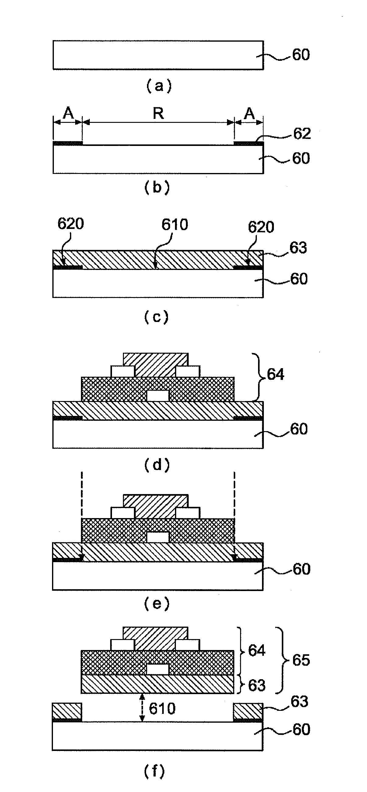
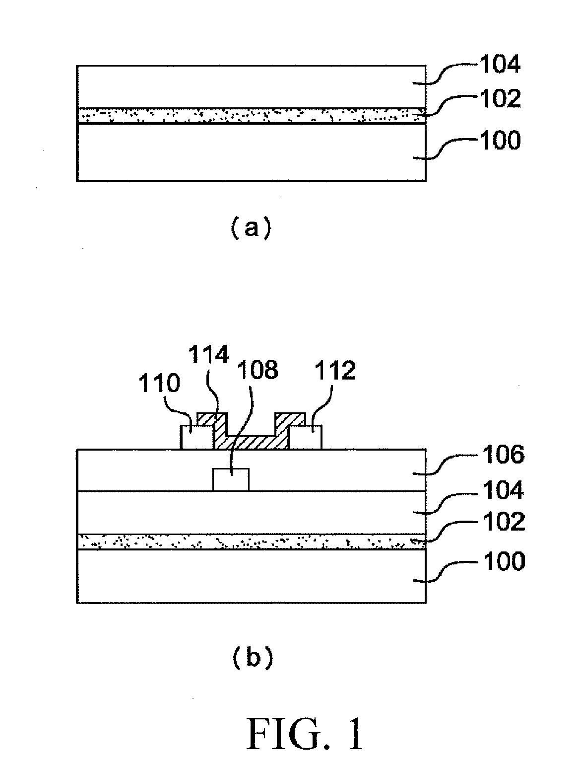
In addition, as the flexible substrate is light and thin, flatness problem easily occurs, so that a device cannot be directly fabricated on a flexible substrate.
As shown in FIG. 1(b), after preparing the desired device, the flexible substrate is separated from the rigid carrier; however, due to the adhesion force of the adhesive layer 102, the flexible substrate cannot be easily separated, and residual adhesive tends to be left after separation, thus influencing the quality of the device.
In addition, the adhesive layer is generally not resistant to the high temperature, so that the method cannot be used in a process requiring high

Method used


Image

  • Method for fabricating a flexible device
  • Method for fabricating a flexible device
  • Method for fabricating a flexible device

Examples


Embodiment Construction

[0020]The term “release region” as used herein refers to a region where a flexible substrate is to be separated from a rigid carrier in the method of the present invention.

[0021]The term “adhesion region” as used herein refers to a region where a flexible substrate is to contact with a rigid carrier through an adhesion promoting layer in the method of the present invention.

[0022]The term “a portion of the flexible substrate layer” as used herein refers to 50% to 99.9%, and preferably 80% to 99.5% of the flexible substrate layer.

[0023]The rigid carrier used in the present invention may be any one known to persons of ordinary skill in the art of the present invention, for example, but not limited to, glass, quartz, a wafer, ceramic, a metal, or a metal oxide.

[0024]The method of the present invention is mainly characterized by: forming an adhesion layer with a given pattern on a rigid carrier before forming a flexible substrate layer, such that a portion of the flexible substrate layer...


PUM

PropertyMeasurementUnit
Adhesion strengthaaaaaaaaaa
Flexibilityaaaaaaaaaa

Abstract

A method for fabricating a flexible device is provided, which includes providing a rigid carrier; forming an adhesion layer with a given pattern on the rigid carrier; forming a flexible substrate layer on the rigid carrier, wherein a portion of the flexible substrate layer contacts with the rigid carrier to form a first contact interface and the remaining contacts with the adhesion layer to form a second contact interface; forming at least one device on the surface of the flexible substrate layer opposite to the first contact interface; and separating the flexible substrate from the rigid carrier through the first contact interface.

Description

BACKGROUND OF THE INVENTION[0001]1. Field of the Invention[0002]The present invention relates to a method for fabricating a flexible device, and in particular to a method for easily separating a device having a flexible substrate from a rigid carrier.[0003]2. Description of the Prior Art[0004]Flat Panel Display (FPD) has currently replaced the conventional Cathode Ray Tube (CRT) and become the mainstream in the market. Known FPDs include, for example, a Liquid Crystal Display (LCD), a Plasma Display Panel (PDP), and an Organic Light Emitting Display (OLED). The FPDs are mostly fabricated after being processed on a rigid substrate (for example, glass). The use of this kind of rigid display is limited due to the lack of flexibility. Therefore, a flexible display with a flexible substrate in place of the traditional glass substrate has become a focus of current research.[0005]The flexible substrates may be classified into three types, including a thin glass substrate, a metal foil subs...

Claims


Application Information

Patent Timeline
IPC IPC(8): B29C39/12B29D7/01
CPCH01L21/6835H01L51/003H01L51/0097Y02E10/549H01L2221/6835H01L2221/68381H01L2221/68318H10K71/80H10K77/111Y02P70/50G09F9/00
Inventor WU, CHUNG-JENLEE, CHUAN ZONGAN, CHIH-MINSHIH, YI-CHUNGHO, CHANG-HONG
Owner ETERNAL MATERIALS CO LTD
Why Eureka
Try Eureka