
System and Method for Co-Channel Interference Measurement and Managed Adaptive Resource Allocation for Wireless Backhaul

a wireless backhaul and cochannel interference technology, applied in the field of wide area wireless data networks, can solve the problems of high implementation cost, sudden increase in total traffic volume, and inability to effectively deploy network resources, and achieve the effect of reducing one or more disadvantages

Active Publication Date: 2012-09-20
BLINQ NETWORKS
View PDF5 Cites 198 Cited by
  • Summary
  • Abstract
  • Description
  • Claims
  • Application Information

AI Technical Summary

Benefits of technology

[0020]Thus, aspects of the present invention provide a system and method for measurement of co-channel interference and also provides systems and methods for managed adaptive resource allocation (MARA) for wireless backhaul based on measurement of co-channel interference, to enable reduced co-channel interference and for increased aggregate data capacity, with particular application to NLOS wireless backhaul. Also provided are computer program products for implementing these methods.
[0021]More particularly, a system and method is provided for measuring co-channel interference in a wireless network with particular application for management of resource allocation for Non Line of Sight (NLOS) wireless backhaul in MicroCell and PicoCell networks. Given the difficulty of predicting the mutual interference between multiple links, DownLink and UpLink co-channel interference is characterized between each Hub and each Remote Backhaul Module Unit periodically during active service. Beneficially, the co-channel interference metrics are used as the basis for intelligently and adaptively managing network resources to substantially reduce interference and / or increase the aggregate data capacity of the network e.g. by grouping of interfering and / or non-interfering links, and managing resource block allocations accordingly, i.e. assigning common resource blocks to weakly interfering links or groups of links, and allocating different resource blocks or orthogonal channels to strongly interfering links or groups of links.
[0022]According to one aspect of the present invention, there is provided a method for managing resource allocations for a plurality of radio links in a wireless network, e.g. a wide area wireless backhaul network, comprising a plurality nodes, each comprising a transmitter and receiver (transceiver), comprising: measuring data, e.g. comprising at least one of relative path loss and signal strength, indicative of co-channel interference, for each of the plurality of radio links, and scheduling resources based on said co-channel interference data to provide at least one of reduced interference between two or more radio links and increased aggregate capacity of two or more radio links.
[0035]Thus, a second aspect of the invention provides a system for managing resource allocations for a plurality radio links in a wireless network, particularly a wide area wireless backhaul network, comprising a plurality nodes each comprising a transmitter and receiver, the system comprising: processor means for measuring data, comprising at least one of relative path loss and signal strength, indicative of co-channel interference, for each of the plurality of radio links, and scheduler means for scheduling resources based on said co-channel interference data to provide at least one of reduced interference between two or more radio links and increased aggregate capacity of two or more radio links.
[0038]Another aspect of the invention provides a method for characterizing co-channel interference between a plurality of radio links in a wireless network, e.g. a wide area wireless backhaul network, comprising a plurality of nodes, each node comprising a transmitter and a receiver, comprising: measuring the relative path loss or signal strength for each of a plurality of the radio links comprising using a predetermined resource block, e.g. within an OFDM frame, to measure the relative path loss or signal strength between multiple radio transmitters and multiple radio receivers. Preferably, the predetermined resource block is reserved across multiple nodes, e.g. across an entire WAN or MAN, to provide for improved dynamic range of the measurement.

Problems solved by technology

Operators of wireless networks face a number of challenges in cost-effectively deploying networks resources to meet recent dramatic increases in the demand for total data capacity.
For example, in 2009, introduction of the iPhone® by one operator in the United States resulted in a sudden massive increase in the total traffic volume, with resultant stress on their network resources to provide the required cell site capacity to satisfy increased user demand.
Although cell splitting, with deployment of small cells, is an attractive option to increasing capacity, existing high capacity backhaul solutions, which depend on fibre and microwave, are costly to implement.
Operators have limited options to meet the increasing capacity demand with existing network technologies.
The disadvantage is that the additional carriers do not increase the Uplink speed since this is effectively limited by the path loss of the large cell and the limited energy per bit which a user terminal can generate.
Although the LTE technology is based on OFDM / MIMO, the uplink performance at the cell edge is not greatly increased, since this is still limited by the energy / bit that is required to compensate for the large path loss and the limited power which a UE (User Equipment) transmitter is able to generate.
Moreover, as operators roll out 4G networks, they are faced with a delicate balancing act.
They must invest heavily in infrastructure for a new air interface knowing that the initial subscriber density will be very low and their investment will not create significant amounts of revenue for several years.
Most operators would expect their 4G investments to generate a net loss until a minimum subscriber density is achieved.
Although such a cautious deployment method makes sense, inter-operator competition for footprint may force operators to be more aggressive, take more risk, and deploy 4G aggressively in an effort to gain market share.
Two key challenges of cell splitting are site acquisition and backhaul.
Considering site acquisition, for macro-cells, the ability to cell split is restricted by the number of available towers or high-rise buildings.
Furthermore, zoning laws may restrict the ability to build new towers and in some jurisdictions, even if they allow a new tower to be built, obtaining a permit can take several years.
High capacity fiber links are available on major high-rise buildings and on many cellular towers, but they are not available for the vast majority of utility poles where an operator may wish to deploy a PicoCell.
Today, a 100BaseT Ethernet link can cost upwards of $1500 / month in the US and Canada, which results in very significant OPEX costs ($18k / year).
The complication is that Microwave Radio operates at higher frequencies and as a result is restricted to Line of Sight (LOS) type deployments.
This is not a major impediment for establishing a link between two elevated sites, which are substantially above the clutter, but it is no longer an option when the PicoCells or Microcells are deployed on lower elevation structures, below clutter, and LOS conditions no longer exist between the PicoCell and a desired aggregation point.
On the other hand, there are a number of other challenges that arise in implementing a NLOS solution.
NLOS Radio Links operate at lower frequencies than LOS Microwave Radio Links, and a larger path loss is expected for a given propagation distance because the signal must travel through obstructions such as buildings, trees, or around small hills.
Reduced directionality, the random nature of obstructions, fluctuating path losses and beam spreading increase the probability of co-channel interference.

Method used


Image

  • System and Method for Co-Channel Interference Measurement and Managed Adaptive Resource Allocation for Wireless Backhaul
  • System and Method for Co-Channel Interference Measurement and Managed Adaptive Resource Allocation for Wireless Backhaul
  • System and Method for Co-Channel Interference Measurement and Managed Adaptive Resource Allocation for Wireless Backhaul

Examples


Embodiment Construction

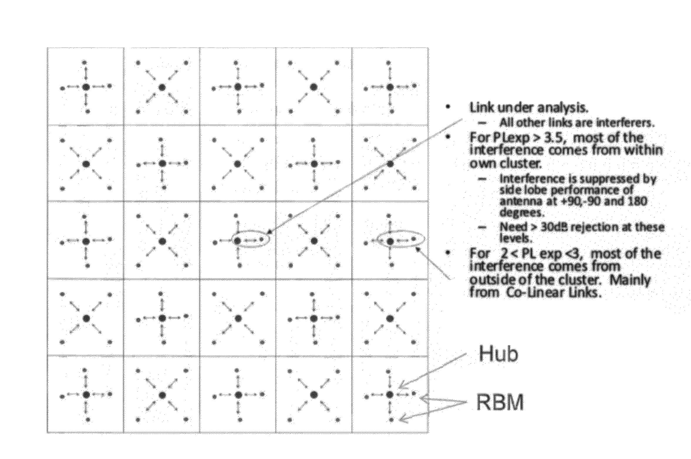
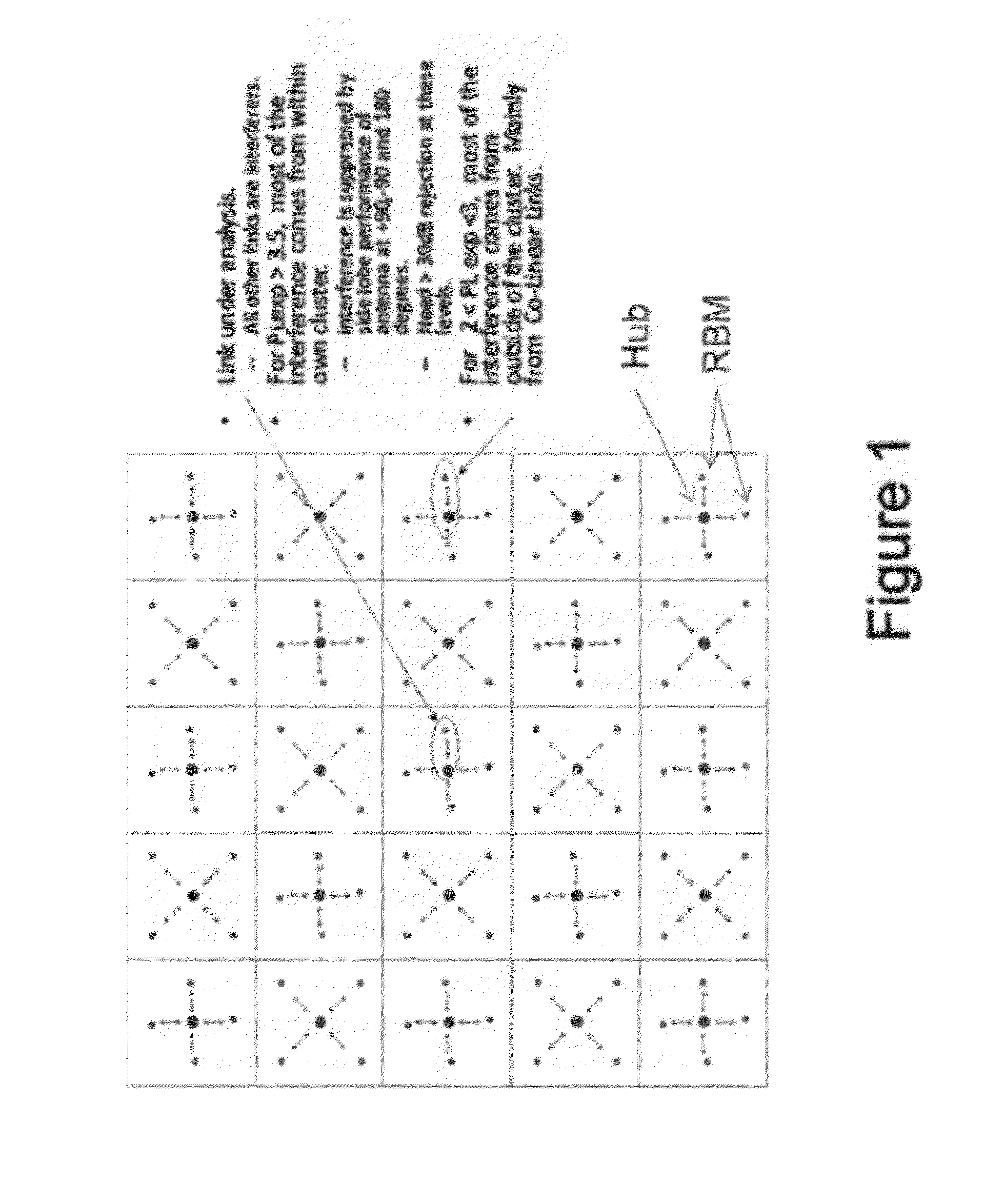
[0051]FIG. 1 illustrates schematically a wide area wireless backhaul communications network comprising a plurality of nodes (N), each comprising a cluster of a Hub (H) and associated Remote Backhaul Modules (RBM), arranged in a grid, which will be used to illustrate systems and methods, according to embodiments of the present invention, for measurement of co-channel interference, control of CINR, and managed adaptive resource allocation. In particular, a novel NLOS backhaul solution is presented, which is capable of providing a cost effective, high capacity, backhaul connection from a Base Station (e.g. a Microcell or PicoCell) to a common aggregation point.

[0052]As represented in FIG. 1, each cell of the grid comprises a cluster of a hub (H) and a number of Remote Backhaul Modules (RBM). The larger, blue dots represent Hubs while the smaller red dots represent remote backhaul modules. In this example, a cluster comprises one Hub and 4 remote backhaul modules. In a real deployment, ...


PUM


Abstract

A system, method, and software are provided for measuring co-channel interference in a wireless network with particular application for management of resource allocation for Non Line of Sight (NLOS) wireless backhaul in MicroCell and PicoCell networks. Given the difficulty of predicting the mutual interference between multiple links, DownLink and UpLink co-channel interference are characterized between each Hub and each Remote Backhaul Module Unit periodically during active service. Beneficially, the co-channel interference metrics are used as the basis for intelligently and adaptively managing network resources to substantially reduce interference and increase the aggregate data capacity of the network e.g. by grouping of interfering and / or non-interfering links, and managing resource block allocations accordingly, i.e. assigning common resource blocks preferentially to weakly interfering links or groups of links and allocating different resource blocks or orthogonal channels to strongly interfering links or groups of links.

Description

CROSS-REFERENCE TO RELATED APPLICATION[0001]This application claims priority from U.S. Provisional Application No. 61 / 382,217, filed 13 Sep. 2010, entitled “System and Method for Co-Channel interference Measurement and Managed Adaptive Resource Allocation for Wireless Backhaul”, which is incorporated herein by reference.TECHNICAL FIELD[0002]This invention relates to wide area wireless data networks, wireless backhaul for high capacity data networks, and to systems and methods for measuring co-channel interference, with particular application to management of resource allocation for Non Line of Sight (NLOS) wireless backhaul in MicroCell and PicoCell networks.BACKGROUND[0003]Operators of wireless networks face a number of challenges in cost-effectively deploying networks resources to meet recent dramatic increases in the demand for total data capacity. This demand is being driven by the introduction of data intensive applications for smart phones, and new mobile devices with video ca...

Claims


Application Information

Patent Timeline
Patent Type & Authority Applications(United States)
IPC IPC(8): H04W72/08H04W24/00
CPCH04W72/082H04B17/382H04B17/345H04W92/12H04W72/541
Inventor BEAUDIN, STEVE ANDRE
Owner BLINQ NETWORKS
Learn More