Phase contrast imaging

a contrast imaging and phase technology, applied in the field of differential phase contrast imaging, can solve the problems of reducing the signal-to-noise ratio at the detector, reducing the visibility of an interference pattern, and reducing the transmittance mean intensity, so as to increase the exposure, reduce the exposure, and increase the contrast-to-noise ratio

Active Publication Date: 2012-09-27
KONINKLIJKE PHILIPS ELECTRONICS NV
View PDF11 Cites 30 Cited by
  • Summary
  • Abstract
  • Description
  • Claims
  • Application Information

AI Technical Summary

Benefits of technology

[0033]In a second step the grating arrangement is moved back, i.e., is inserted into the setup by, e.g., a step motor. The position where the grating arrangement is inserted can be controlled. Hence, it is possible to indicate this position within the previously produced absorption image directly on a screen in form of a frame covering the same region that the system of gratings affects in a synchronous way. The physician who performs the X-ray scan may be able to choose the exact position of the centre of this frame on the screen and can thus position that frame to a region-of-interest (ROI) that he is most interested in because the absorption image indicates a potential abnormality there. At this position the grating arrangement is synchronously inserted into the X-ray path to now produce a PCI image of this ROI. This allows the physician to receive a PCI image focused on that ROI with higher contrast-to-noise ratio without further increasing the X-ray dose exposed to the human body. The physician might decide to reduce the exposure in the first step

Problems solved by technology

The use of gratings within the transmitted X-ray beam face the problem, that non-focused gratings produce a less modulated absorption by themselves especially outside of the central region of the field-of-view (FOV), resulting in a decreased visibility of an interference pattern, a decreased transmitted mean intensity, and thus a lower signal-to-noise ratio at a detector.
Therefore, the absorption image has either lower contrast-to-noise ratio or the radiation dose must be increased which the human body is potentially harmfully exposed.
All that leads to a decreased mean X-ray intensity and a decreased visibilit

Method used


Image

  • Phase contrast imaging
  • Phase contrast imaging
  • Phase contrast imaging

Examples


Embodiment Construction

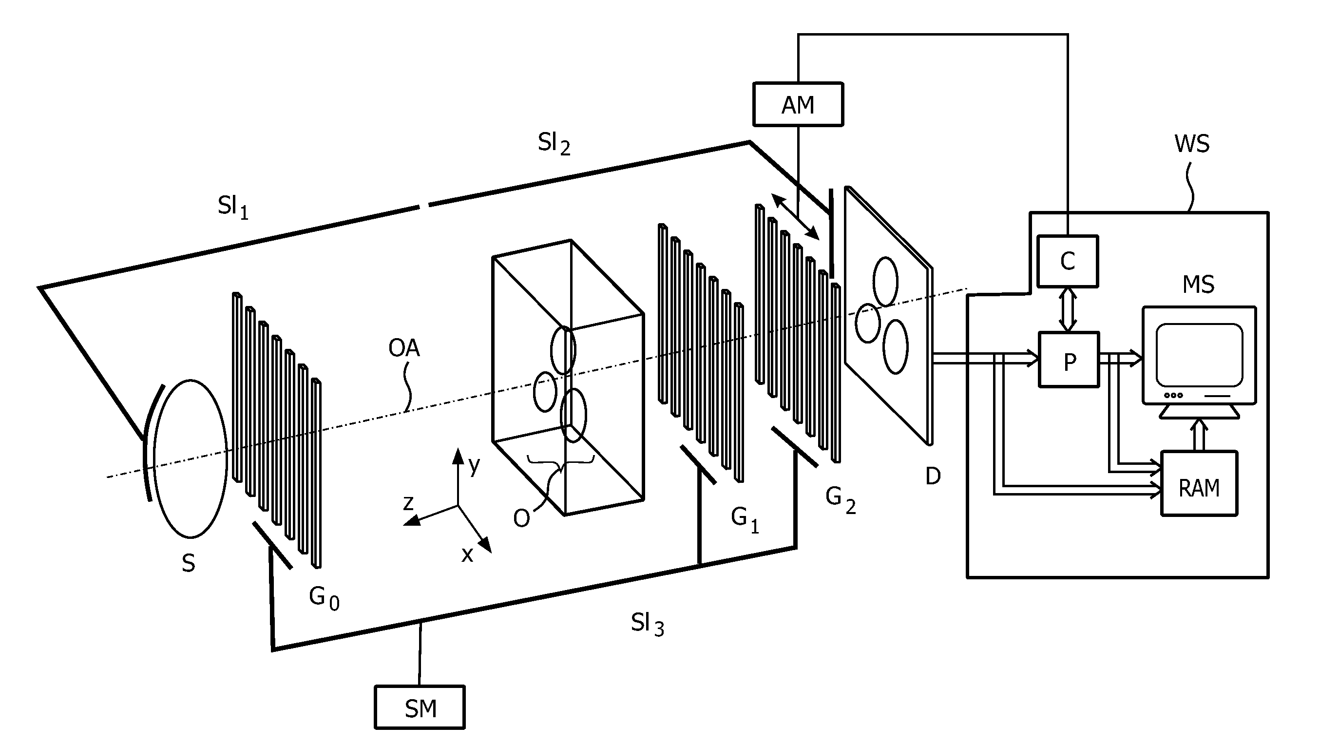
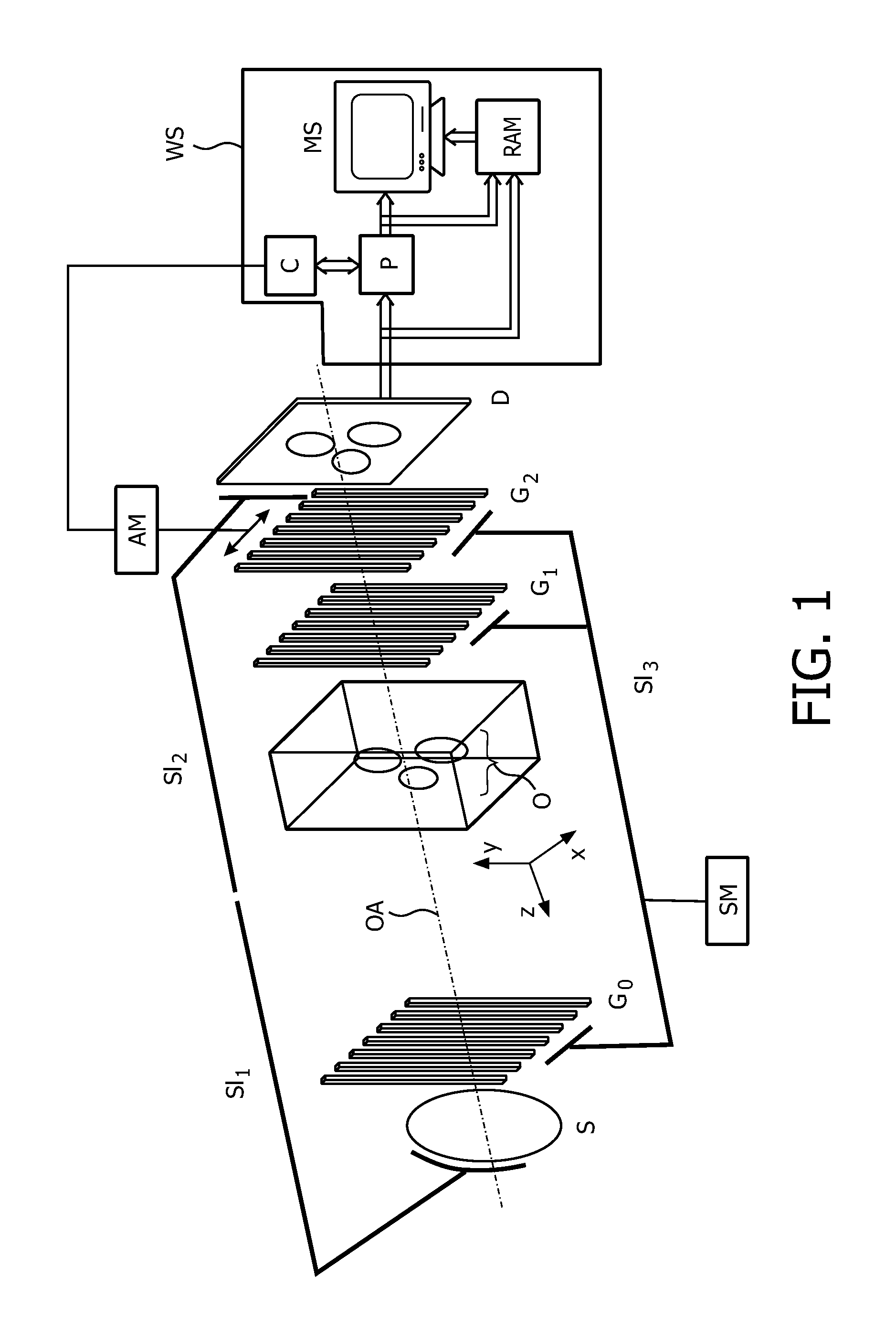
[0044]FIG. 1 is a schematically representation of a grating setup for a Talbot-Lau type hard-X-ray imaging interferometer, which may be used in accordance with the invention. The device will be described in the following in the context of a brief description of the functionality of the different parts of the device.

[0045]Using this kind of interferometer leads to the effect that interfering X-ray beams are not completely separated but merely sheared by a small angle, so that they pass through different, closely spaced parts of the sample. The hard-X-ray imaging interferometer comprises an incoherent X-ray source S, a source grating G0 for achieving spatial beam coherence, a diffractive grating G1 (herein also referred to as phase grating) having a plurality of equidistant X-ray absorbing strips extending in parallel in a direction normal to the interferometer's optical axis, which serves as a phase-shifting beam splitter and is placed in downstream direction behind the object, an ab...


PUM


Abstract

X-ray devices for Phase Contrast Imaging (PCI) are often built up with the help of gratings. For large field-of-views (FOV), production cost and complexity of these gratings could increase significantly as they need to have a focused geometry. Instead of a pure PCI with a large FOV, this invention suggests to combine a traditional absorption X-ray-imaging system with large-FOV with an insertable low-cost PCI system with small-FOV, The invention supports the user to direct the PCI system with reduced FOV to a region that he regards as most interesting for performing a PCI scan thus eliminating X-ray dose exposure for scanning regions not interesting for a radiologist. The PCI scan may be generated on the basis of local tomography.

Description

FIELD OF THE INVENTION[0001]The invention relates to differential phase contrast imaging (PCI). In particular, the invention relates to a device and method for differential phase contrast imaging.BACKGROUND OF THE INVENTION[0002]The traditional X-ray systems used for medical applications are mainly based on the different absorption of X-rays in matter resulting in projection images formed by the accumulated absorption of the X-rays along a line. Yet, matter does not only influence the absorption but also the refraction of X-rays. This characteristics promises higher X-ray contrast between human tissue types than the conventional absorption-based imaging and hence can represent a future improvement. A possible setup for facilitating PCI is based on gratings.[0003]The use of gratings within the transmitted X-ray beam face the problem, that non-focused gratings produce a less modulated absorption by themselves especially outside of the central region of the field-of-view (FOV), resulti...

Claims


Application Information

Patent Timeline
IPC IPC(8): G01N23/04
CPCA61B6/00A61B6/4291A61B6/484A61B6/4441
Inventor GELLER, DIETERENGEL, KLAUS JUERGENVOGTMEIER, GEREONKOEHLER, THOMASROESSL, EWALD
Owner KONINKLIJKE PHILIPS ELECTRONICS NV
Why Eureka
Try Eureka