
Photonic Crystal Three-Port Circulator

a three-port circulator and photonic crystal technology, applied in the direction of optical elements, optical waveguide light guides, instruments, etc., can solve the problems of affecting the overall performance of the designed optical circuit, the deformation of the design optical circuit, and the inability to complete normal logic functions, etc., to achieve low-loss light transmission and high light isolation effects, easy integration with other photonic effects, and simple and compact structure

Inactive Publication Date: 2012-09-27
SHENZHEN UNIV
View PDF4 Cites 23 Cited by
  • Summary
  • Abstract
  • Description
  • Claims
  • Application Information

AI Technical Summary

Benefits of technology

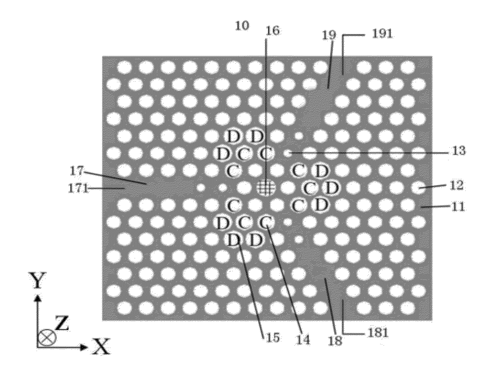
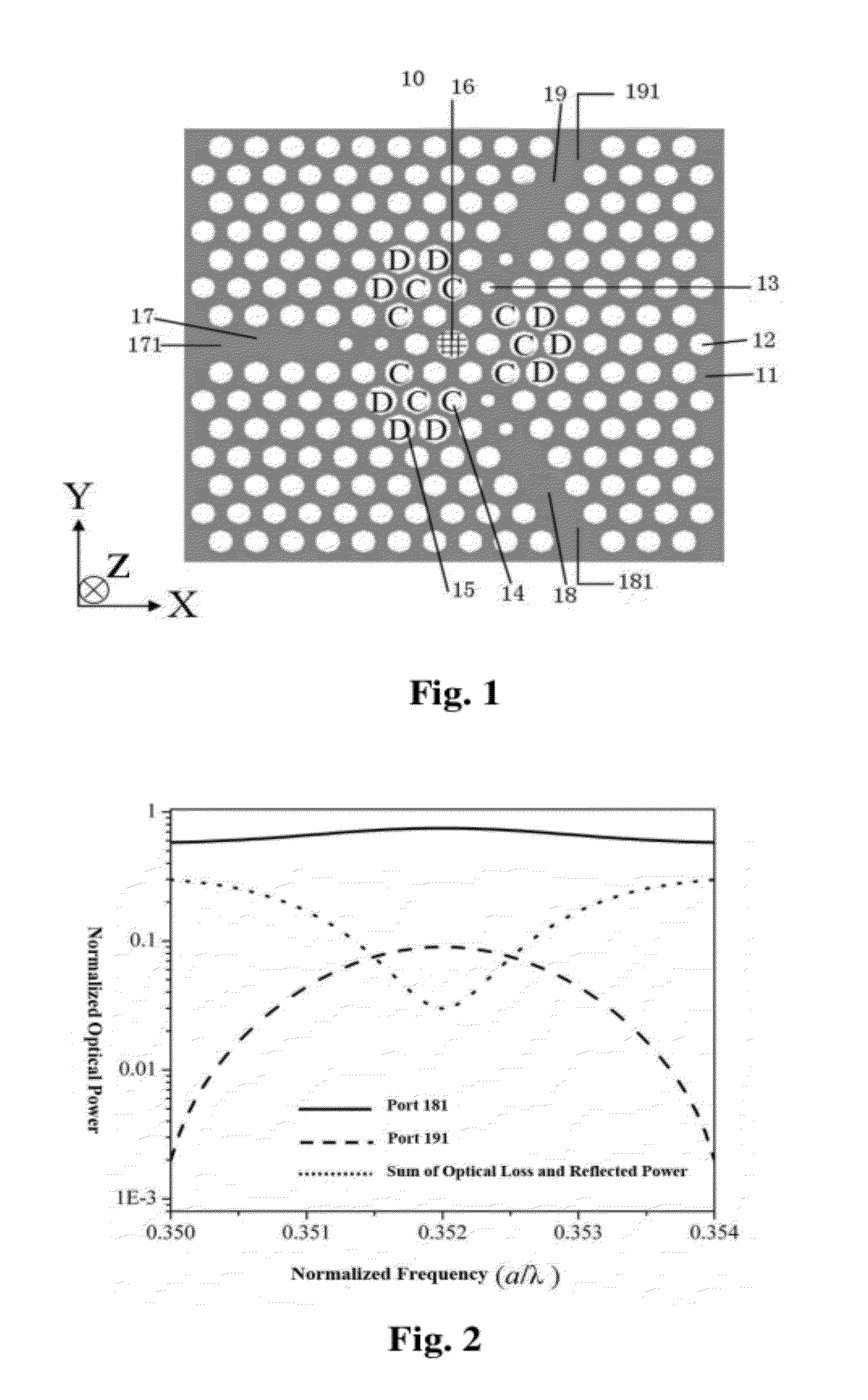
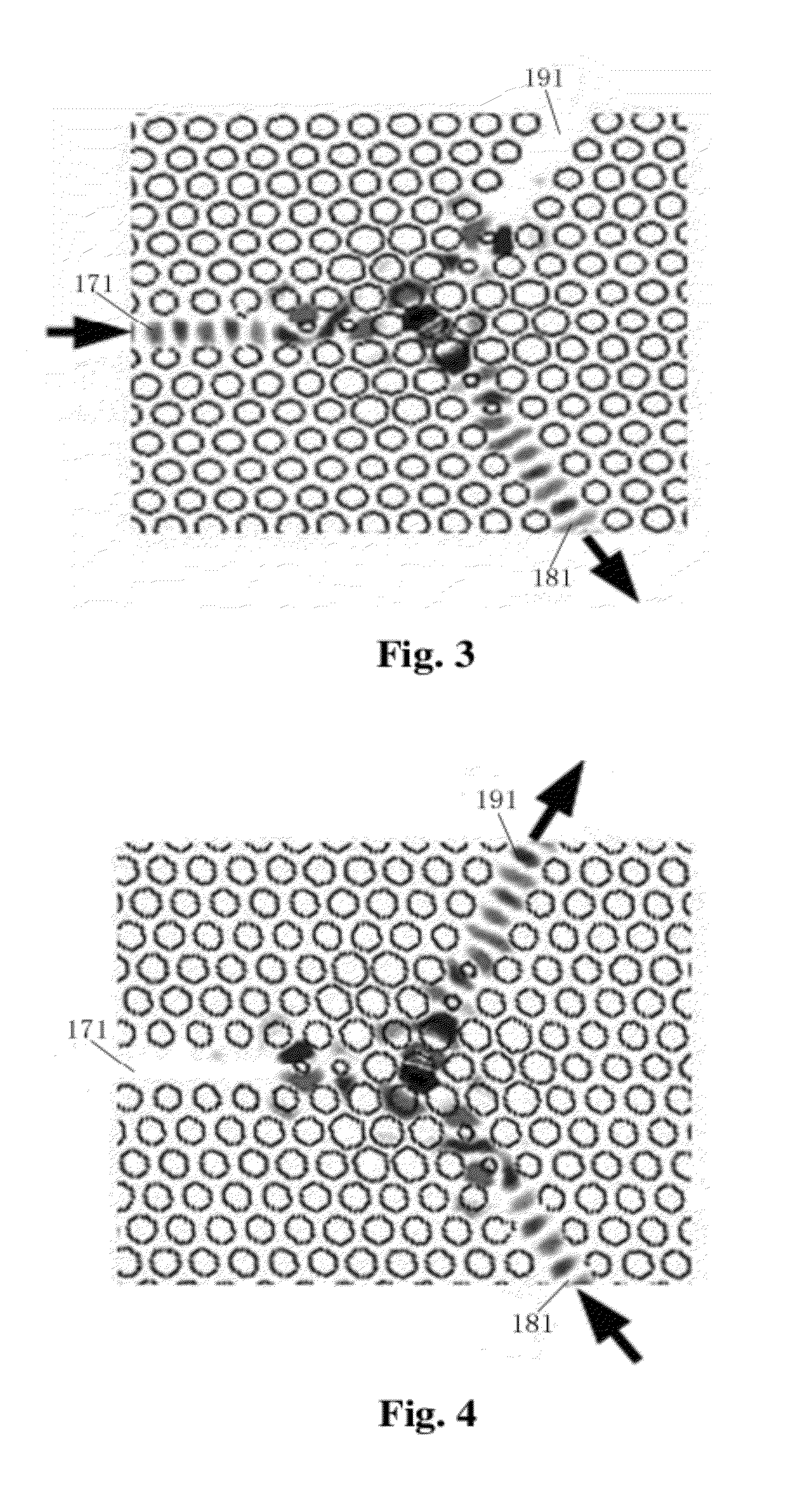
[0014]The photonic crystal three-port circulator provided by the invention utilizes the optical activity of the magneto-optical cavity at the center of the photonic crystal three-port circulator to achieve the low-loss light transmission and high light isolation effects on different waveguides and to successfully realize circular transmission of light in single rotational direction among three waveguide ports. Moreover, the photonic crystal three-port circulator has a simple and compact structure, can be easily integrated with other photonic crystal devices, and plays an important role in the isolation of light signal crosstalk in the integration of photonic crystal logic devices, thereby guaranteeing the normal operation of an optical circuit system.
[0015]Furthermore, in the photonic crystal three-port circulator provided by the invention, two second air columns are arranged at the position in each waveguide close to the magneto-optical cavity. In the light transmission state, the second air columns have the function of coupling the magneto-optical cavity and the waveguides. In the light isolation state, the second air columns have the function of isolating the magneto-optical cavity and the waveguides. In addition, a plurality of third air columns and a plurality of fourth air columns are arranged between every two waveguides, close to the magneto-optical cavity. Due to the arrangement of a plurality of the third air columns and a plurality of the fourth air columns, the interference between the waveguides is reduced and the transmission efficiency of the waveguides is improved as well.

Problems solved by technology

With the increase of the integration scale of the logic devices, the problem of mutual interference among components in an optical circuit has become more apparent.
If this problem is not properly solved, the overall performances of the designed optical circuit can be greatly degraded, and normal logic functions cannot be even completed under severe cases.
However, being mainly based on bulky magneto-optical materials, the traditional magneto-optical circulator has large volume and thus is not suitable to be integrated with photonic crystal devices.

Method used


Image

  • Photonic Crystal Three-Port Circulator
  • Photonic Crystal Three-Port Circulator
  • Photonic Crystal Three-Port Circulator

Examples


Embodiment Construction

[0021]The invention relates to a photonic crystal three-port circulator. Detailed description is given to the technical proposal of the invention with the attached drawings.

[0022]As illustrated in FIG. 1, the invention provides a photonic crystal circulator 10, which comprises a dielectric background material 11, a plurality of first air columns 12, six second air columns 13, a plurality of third air columns 14 (air columns C), a plurality of fourth air columns 15 (air columns D), a magneto-optical cavity (not marked), a first waveguide 17, a second waveguide 18 and a third waveguide 19, wherein a plurality of the first air columns 12, the six second air columns 13, a plurality of the third air columns 14 and a plurality of the fourth air columns 15 are symmetrically arranged in the dielectric background material 11 in the form of triangular lattice; the magneto-optical cavity is arranged at the center of the photonic crystal three-port circulator 10 and comprises a magneto-optical ...


PUM


Abstract

Taught is a photonic crystal three-port circulator, which comprises a dielectric background material and a plurality of first air columns which are symmetrically arranged in the form of triangular lattice in the dielectric background material. The photonic crystal three-port circulator also comprises a magneto-optical cavity and three waveguides, wherein the magneto-optical cavity is arranged at the center of the photonic crystal three-port circulator; the three waveguides are symmetrically distributed around the magneto-optical cavity; and each waveguide comprises a waveguide port which is arranged at the position in the waveguide far away from the magneto-optical cavity. The photonic crystal three-port circulator realizes circular light transmission in single rotational direction from any one of the waveguide ports to another next to it, has a simple and compact structure, and can be easily integrated with other photonic crystal devices.

Description

FIELD OF THE INVENTION[0001]The invention relates to a photonic crystal three-port circulator, in particular to a dielectric-substrate-air-column type photonic crystal three-port circulator.BACKGROUND OF THE INVENTION[0002]The increasing development of the modern all-optical information processing technology lays a solid foundation for the realization of optical circuit integrated chips. In 1987, E. Yablonovitch and S. John proposed the concept of photonic crystal. Later, photonic crystal is subjected to in-depth study continually and considered as one of the most potential photonic devices for realizing a new generation of all-optical integrated chips. Photonic crystal is a novel artificial material which is formed by the periodic arrangement of dielectric materials in space. Just like the fact that semiconductor materials can manipulate electrons, photonic crystal can control and operate photons as well. After 20 years' development, significant progress has been made in the aspect...

Claims


Application Information

Patent Timeline
Patent Type & Authority Applications(United States)
IPC IPC(8): G02B6/10
CPCB82Y20/00G02B6/1225G02F2202/32G02F1/0955G02B2006/12157
Inventor OUYANG, ZHENGBIAOWANG, QIONG
Owner SHENZHEN UNIV
Learn More