Enclosed offshore tank for storing crude oil

a technology for offshore tanks and crude oil, which is applied in the direction of auxilaries, floating buildings, containers, etc., can solve the problems of inability to store, serious production compromise, and inability to build a conventional production platform, and achieve the effect of avoiding heat loss to the environmen

Inactive Publication Date: 2012-10-04
KINGTIME INT
View PDF8 Cites 9 Cited by
  • Summary
  • Abstract
  • Description
  • Claims
  • Application Information

AI Technical Summary

Benefits of technology

[0034]The enclosed offshore tank described above is used for preventing deposition of wax in solid form and for storing crude oil in a flowable form. The offshore tank is suitable for containing paraffinic crude oil or where the crude oil needs to be kept at an elevated temperature for flow assurance. Wax deposition in solid form is avoided by maintaining the crude oil at a temperature of approximately 8° C. above its corresponding wax appearance temperature. Homogenization of the oil and re-suspension of sludge formed is achieved by operating at least one rotary jet mixer at the bottom of the offshore tank.
[0035]The piping means receives heated fluid from a heating source. The at least one piping means is connected to at least conduit means which supplies the heated fluid to the piping means. The piping means is embedded in a reinforced concrete layer that radiates heat to the water and / or crude oil in the offshore tank. The reinforced concrete layer embedding the piping means is underlayed with a heat insulating layer to avoid heat loss to environment. The heat insulating layer is protected from damage by a base made of steel plate, reinforced concrete and or any other protecting tank material. The heat insulating layer can take the form of a specialist coating material for e.g. Alderley Material's ContraTherm C55 Subsea System or alternatively can be a mixture of expanded perlite material mixed with concrete.

Problems solved by technology

In some areas such as remote locations far away from existing infrastructures, even in relatively shallow waters, the cost of building a conventional production platform cannot be justified based on the amount of production anticipated from the wells.
In the event that this was not possible then production would seriously be compromised.
The above examples will not in certain circumstances be able to store and retrieve crude oil containing wax or crude oil that needs to be kept at an elevated temperature to assist flow assurance.
The accumulation of wax in wells, flowlines and storage facilities is a common problem.
In the past, many literature reviews stated that oils with a paraffin concentration level above 10% can cause severe deposition and flow problems.
However, even low paraffin content crudes (less than 1%) can have severe deposition problems.
Although, for many years, wax properties of oils have been characterized by cloud point and pour point measurements, these measurements give only a general understanding of temperatures at which wax deposition and crude oil gelling will become a problem.
However, the mass transport due to the Brownian motion is small enough to be neglected by many researchers.
However, it is not characteristic for a vertical flow line.
The formation of the paraffin deposits in heat exchange surfaces, in other words the formation of deposits in subsea pipelines, and in the bulk of the fluid, can seriously jeopardise petroleum production.
If control of wax deposition is not effective, the wax deposits can build up significantly with time and cause disruption of production, reduction of throughput or reduction of storage volume and the inability to offload the stored crude.
Subsea pipeline, production and storage facilities are susceptible to wax deposits and asphaltene precipitates, induced by lower temperatures.
Although this can usually be achieved naturally for wellbores and wellheads installed on the seabed, it is often not possible to maintain this high temperature in topside facilities.
Oil temperature arriving at different facilities may be limited due to processing concerns or by the temperature rating of equipment.
During late life, reservoir temperature may drop to a point that oil arrival temperatures are substantially below the cloud point leading to significant deposition.

Method used


Image

  • Enclosed offshore tank for storing crude oil
  • Enclosed offshore tank for storing crude oil
  • Enclosed offshore tank for storing crude oil

Examples


Embodiment Construction

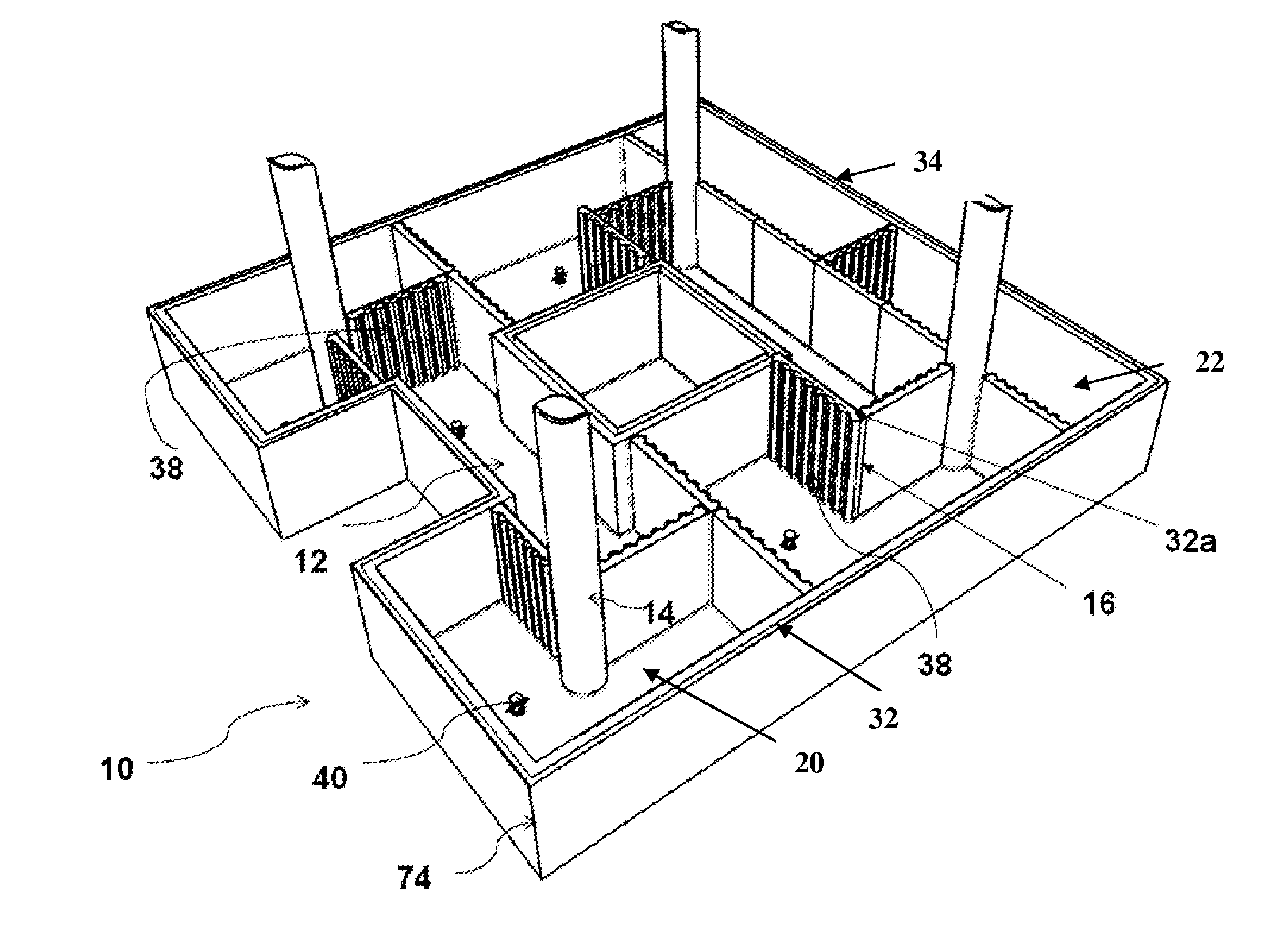
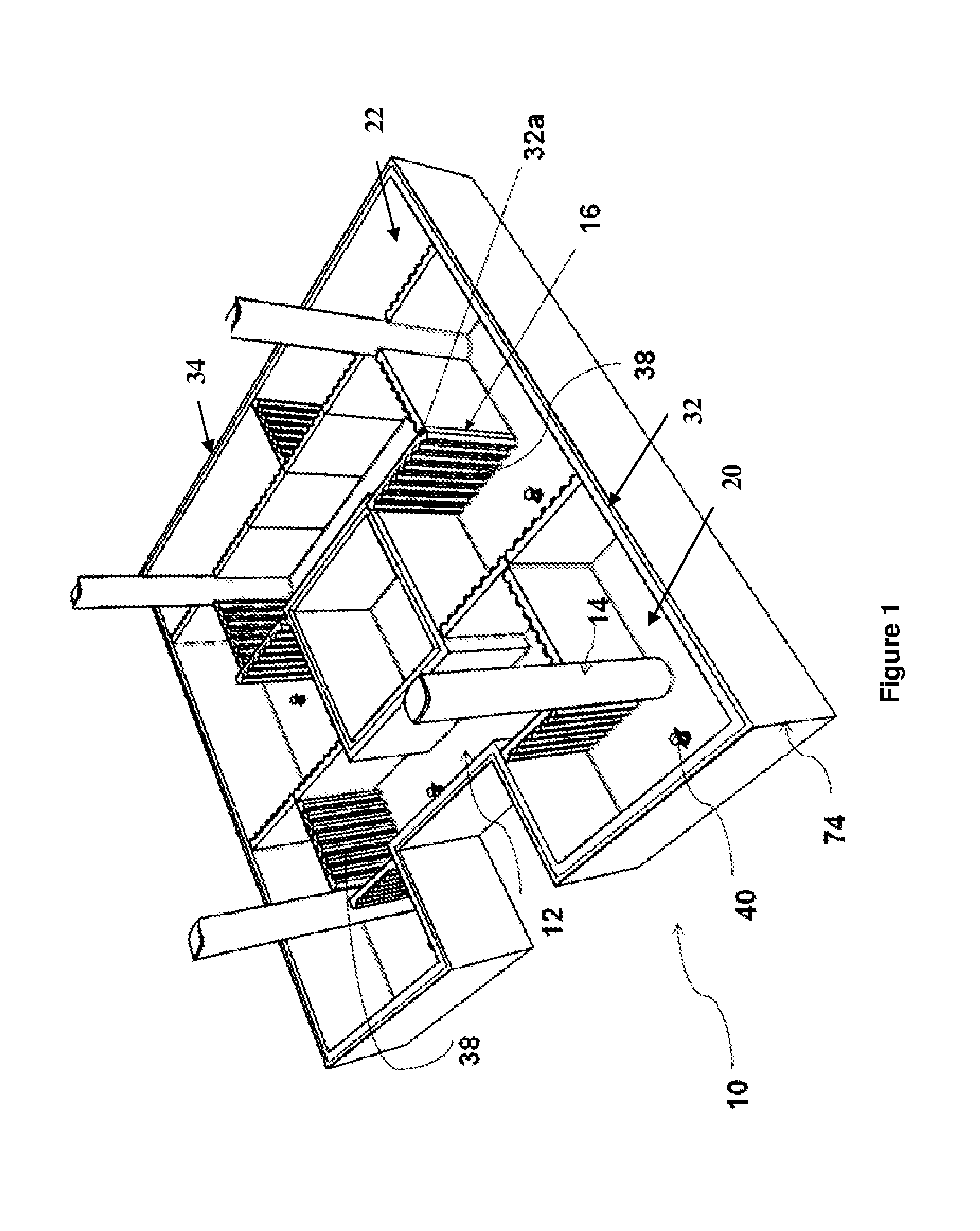
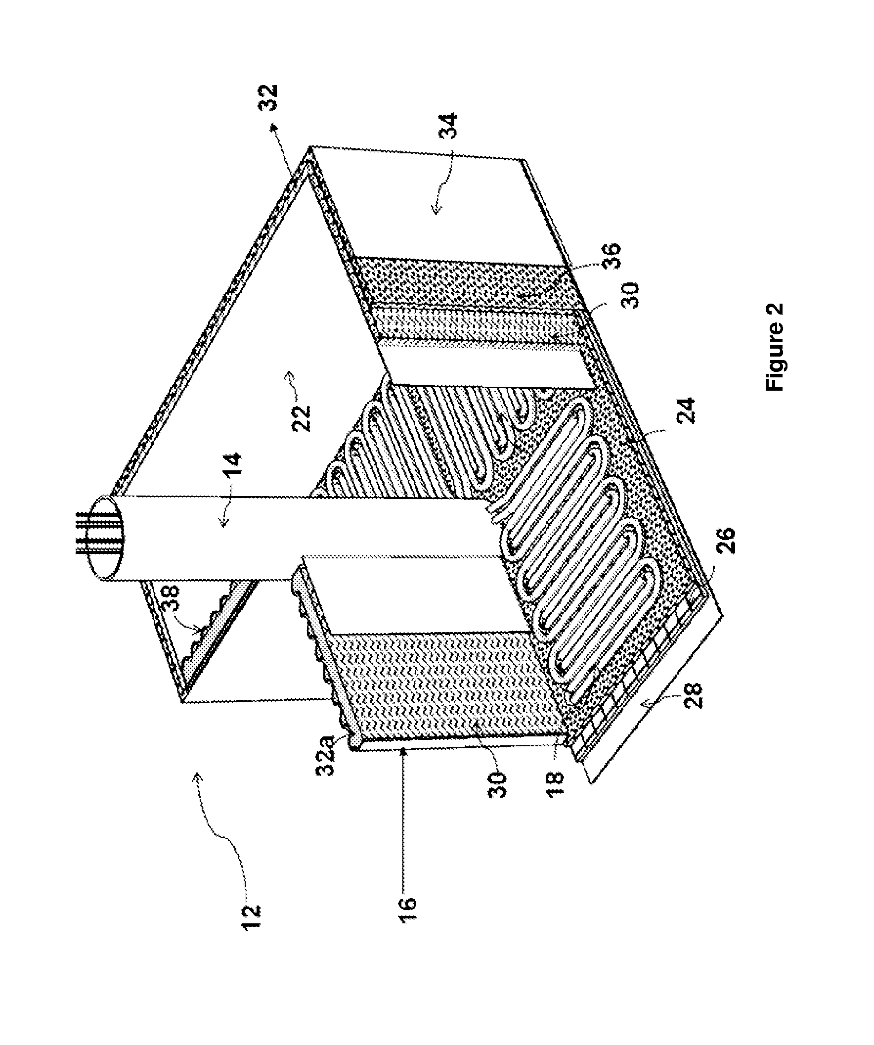
[0053]A variety of techniques have been employed in order to reduce problems associated with flow assurance caused by various reasons including crystallization of paraffin during production, transportation and / or storage of crude oil. Rate of paraffin / wax deposition in an enclosed offshore tank or storage system can be reduced by injection of paraffin / wax dispersant chemicals, which can reduce deposition rates by up to five times. However, operating an enclosed offshore tank storing crude oil at temperatures above wax appearance temperature is preferable. In the present invention, the term paraffin and wax are used interchangeably. The present invention relates to an enclosed offshore tank requiring minimum intervention and built in redundancy for storing crude oil in a flowable form where the problems associated with flow assurance are prevented. The enclosed offshore tank comprises a floor, an insulated top cover and perimeter wall secured to a floor forming the offshore tank. In ...


PUM


Abstract

An enclosed offshore tank for storing crude oil in a flowable form where the problems associated with flow assurance are prevented. The enclosed offshore tank includes a floor, an insulated cover and perimeter wall secured to a floor forming the offshore tank. The enclosed offshore tank can include a means of floor heating, wherein the floor is provided with piping which receives heated fluid to heat the crude oil. The perimeter wall can have an inner wall and an outer wall forming an annulus, wherein a heated fluid from a heating source fills the annulus to heat the crude oil. A microwave heating system can include at least one microwave generator, at least one waveguide and at least one radiating element to indirectly heat crude oil in the offshore tank.

Description

FIELD OF INVENTION[0001]The present invention relates to an enclosed offshore tank for storing crude oil.BACKGROUND ART[0002]Oil and gas produced from offshore wells must be transported from the production site to land-base for subsequent refining and storing. Transportation facilities for subsequent processing are also needed. In some areas such as remote locations far away from existing infrastructures, even in relatively shallow waters, the cost of building a conventional production platform cannot be justified based on the amount of production anticipated from the wells. Accordingly, there are classes of wells that could be economically drilled and oil extracted if the cost of fabricating a suitable production platform is economical. In such cases, an adequate submerged or floating storage facility can make production from the site economically desirable. An example of an economical, mobile offshore oil drilling, production and storage platform (MOPSU) is described in U.S. paten...

Claims


Application Information

Patent Timeline
Patent Type & Authority Applications(United States)
IPC IPC(8): H05B6/64
CPCB63B25/16B63B35/44B63B2035/4486B65D90/022B65D88/744B65D88/78B65D90/0066B63J2/14
Inventor NADARAJAH, NAGENDRAN C.DE RAJ, RENATA ANITASUPPIAH, MAHENDRANGROZESCU, IONEL VALERIU
Owner KINGTIME INT
Why Eureka
Try Eureka