Method of depositing silicon on carbon nanomaterials

a carbon nanomaterial and carbon nanotechnology, applied in the field of silicon depositing on carbon nanomaterials, can solve the problems of high lifetime cost for consumers, short driving range for most automobile owners, and rapid loss of capacity of silicon-based anodes, etc., and achieve the effect of increasing the surface area of carbon nanomaterials and increasing the pore volume of carbon nanomaterials

Inactive Publication Date: 2012-10-18
APPLIED SCI
View PDF6 Cites 129 Cited by
  • Summary
  • Abstract
  • Description
  • Claims
  • Application Information

AI Technical Summary

Benefits of technology

[0018]The method may further include heating the carbon nanomaterial at a temperature between about 100° C. to 1200° C. in the presence of an oxidizing gas prior to depositing the silicon coating. The carbon nanomaterial i...

Problems solved by technology

However, currently available lithium-ion battery technologies are limited to system level energy densities of less than 200 Wh/kg, which results in unacceptably short driving range for most automobile owners.
In addition, lithium ion batteries have a short cycle life and are expensive to produce, leading to high lifetime costs for the consumer.
Silicon, which has a theoretical capacity of up to 4200 mAh/g, is one such material; however, silicon-based anodes exhibit a rapid loss of cap...

Method used


Image

  • Method of depositing silicon on carbon nanomaterials
  • Method of depositing silicon on carbon nanomaterials
  • Method of depositing silicon on carbon nanomaterials

Examples


example 1

[0065]Samples of carbon nanofiber powder were formed by de-bulking carbon nanofibers (PR-25-XT-PS from Applied Sciences, Inc.) into a pelletized form using wet mixing or powder processing methods. The powder samples were exposed to carbon dioxide at a temperature of about 950° C. for 2 hours at a carbon dioxide flow rate of 2 liters per minute (LPM) to increase the surface area and porosity prior to coating with silicon.

[0066]Table 1 below shows the effect of this form of oxidation under various conditions on the surface area of the carbon nanofibers prior to coating with silicon.

TABLE 1Effect of carbon dioxide oxidation on the surface of carbon nanofibersSurface areaPore volumeAvg. Pore diameter(m2 / g)(cm3 / g)(nm)Carbon nanofiber680.148.2powder (baseline)Carbon nanofiber1810.286.1powder (CO2etched)

The sample of carbon dioxide treated nanofiber powder was then coated with silicon by exposure to silane gas at 500° C. for 10 minutes where the silane flow rate was 2 LPM. The silicon coat...

example 2

[0067]To study the effect of oxidation of the silicon coating on electrochemical performance, several strips of carbon nanofiber (CNF) veil samples obtained from Applied Sciences, Inc. were coated with silicon by exposure to silane gas at 500° C. for 15 minutes and split into two groups. One group was tested as-is while the other group received an oxidation treatment in air at 200° C. for 4 hours. The electrochemical performance of the two groups was evaluated in a coin half-cell configuration. The oxidized sample showed a capacity retention of 74% between cycles 2 to 51, which was an improvement over the non-oxidized sample, which showed a capacity retention of 62%.

example 3

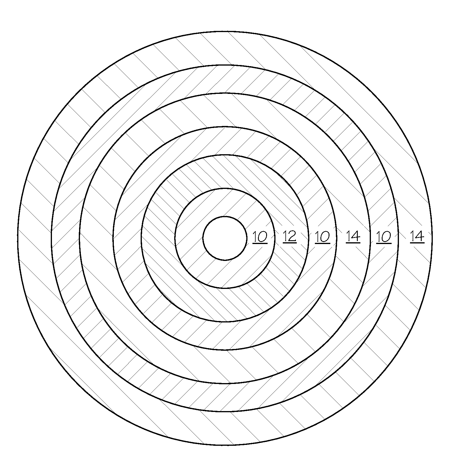
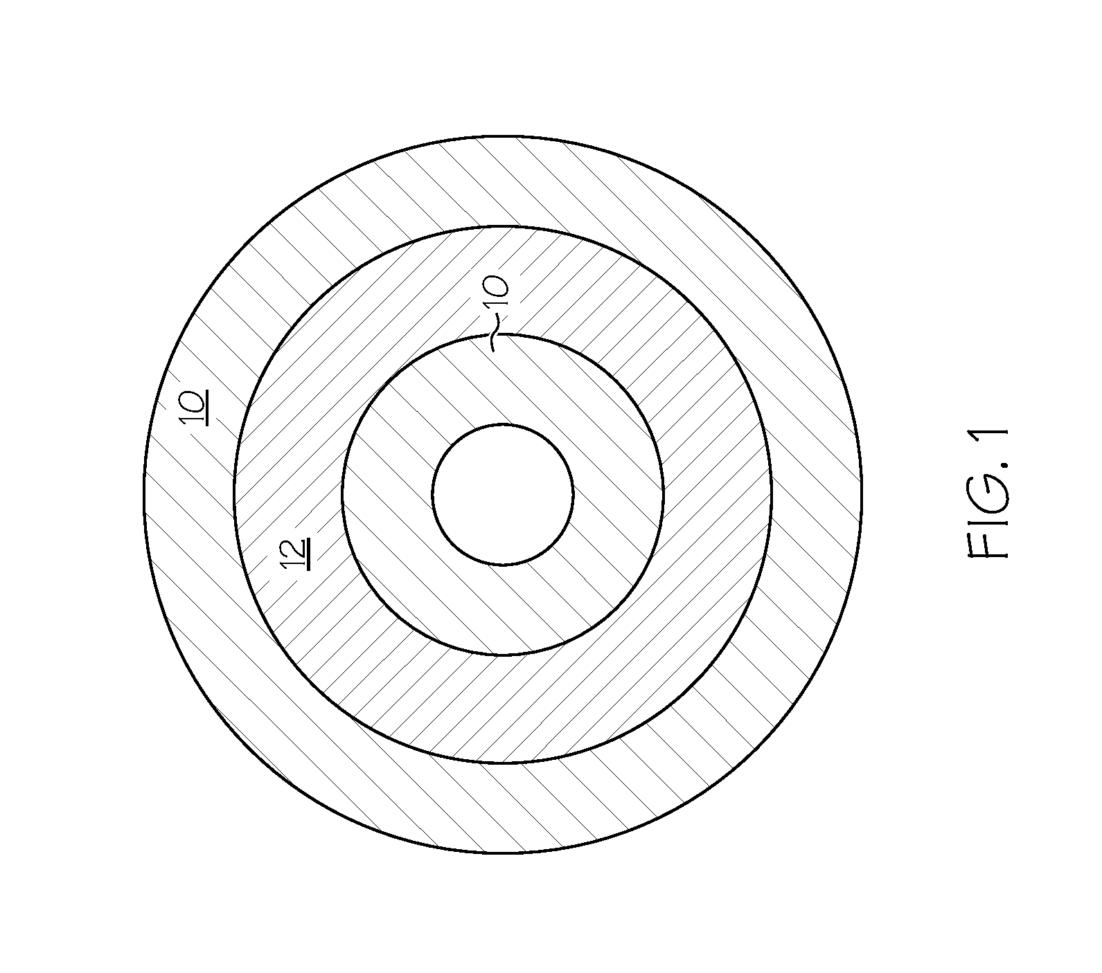
[0068]A nanomat comprised of carbon nanofibers from Applied Sciences, Inc. was coated with silicon by exposure to silane gas at a temperature of 500° C. for 2 minutes and was then coated on its exterior with a 5-10 nm thick layer of carbon by magnetron sputtering over the silicon-coated surface. The sample retained close to 80% of its initial capacity in about 200 cycles.


PUM

PropertyMeasurementUnit
Temperatureaaaaaaaaaa

Abstract

A method of depositing silicon on carbon nanomaterials such as vapor grown carbon nanofibers, nanomats, or nanofiber powder is provided. The method includes flowing a silicon-containing precursor gas in contact with the carbon nanomaterial such that silicon is deposited on the exterior surface and within the hollow core of the carbon nanomaterials. A protective carbon coating may be deposited on the silicon-coated nanomaterials. The resulting nanocomposite materials may be used as anodes in lithium ion batteries.

Description

CROSS REFERENCE TO RELATED APPLICATIONS[0001]This application claims the benefit of U.S. Patent Application Ser. No. 61 / 390,800, entitled METHOD OF DEPOSITING SILICON AND SULFUR ON CARBON NANOMATERIALS AND FORMING AN ANODE AND CATHODE FOR USE IN LITHIUM ION BATTERIES filed Oct. 7, 2010. This application also claims the benefit of U.S. patent application Ser. No. 12 / 107,254, entitled METHOD OF DEPOSITING SILICON ON CARBON MATERIALS AND FORMING AN ANODE FOR USE IN LITHIUM ION BATTERIES filed Apr. 22, 2008. The entire contents of said applications are hereby incorporated by reference.BACKGROUND OF THE INVENTION[0002]Embodiments of the invention relate to a method of depositing silicon on the exterior surface and within the hollow core of carbon nanomaterials such as vapor grown carbon nanofibers, nanomats and nanofiber powders to produce high capacity electrodes having high capacity retention rates for use in lithium ion batteries.[0003]The automotive industry is currently pursuing ene...

Claims


Application Information

Patent Timeline
IPC IPC(8): H01M4/583C23C16/02C23C14/35B29D99/00B05D7/00C23C16/24B82Y30/00
CPCB82Y30/00C23C14/02C23C14/0605C23C14/35C23C14/5853C23C16/401C23C16/56H01M4/0426H01M4/0428H01M4/0471H01M4/133H01M4/134H01M4/1393H01M4/1395H01M4/366H01M4/386H01M4/587H01M4/625Y02E60/10
Inventor BURTON, DAVID J.LAKE, MAX L.NAZRI, MARYAMPALMER, ANDREW C.
Owner APPLIED SCI
Why Eureka
Try Eureka