

Fuel cell system and method of stopping fuel cell system
a fuel cell and system technology, applied in the direction of fuel cells, solid electrolyte fuel cells, electrical equipment, etc., can solve the problems of oxidation of the carbon component material of the cathode, the cathode electrode potential is raised, etc., to inhibit the oxidation of the cathode component material, and reduce the variation of the cathode total pressure
- Summary
- Abstract
- Description
- Claims
- Application Information
AI Technical Summary
Benefits of technology
Problems solved by technology
Method used
Image

Examples
first embodiment
A. First Embodiment
A-1. Configuration of First Embodiment
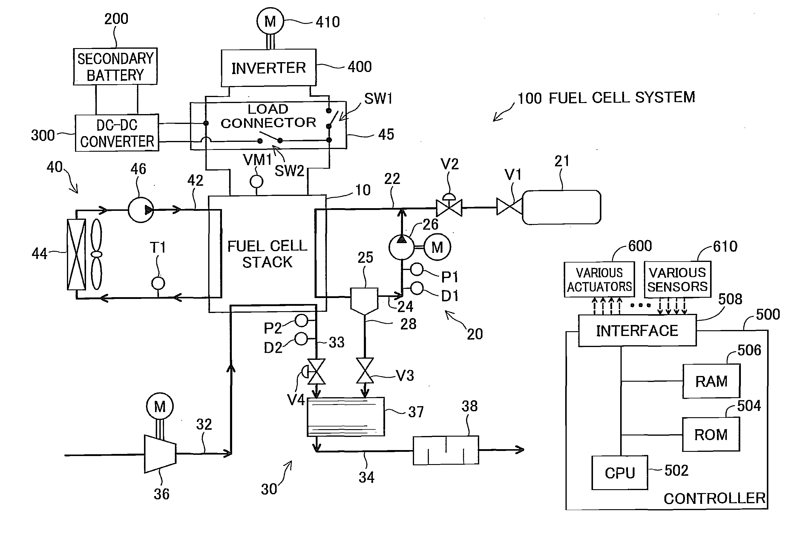
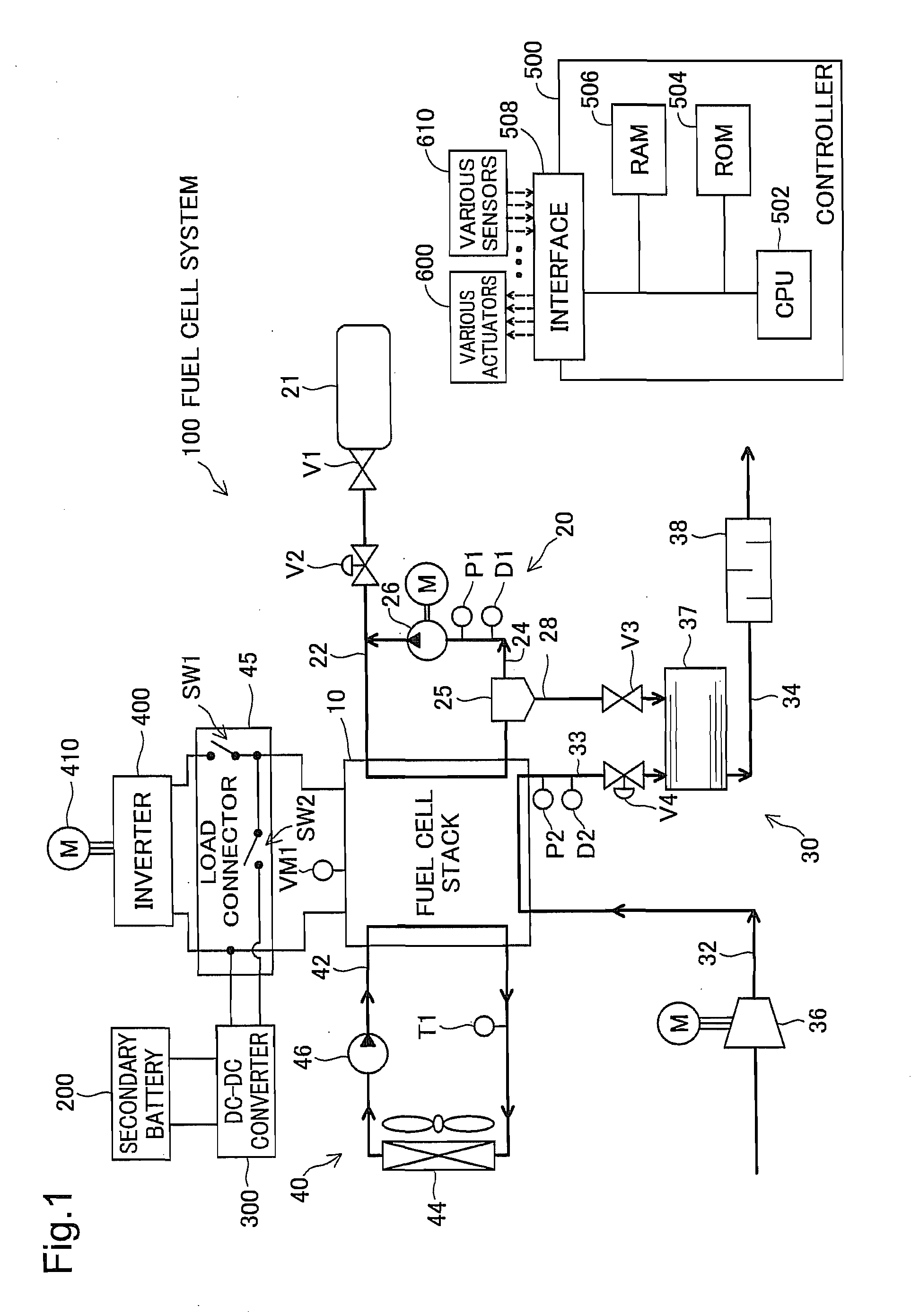
[0116]FIG. 1 illustrates the general configuration of an electric vehicle with a fuel cell system 100 according to a first embodiment of the invention. As illustrated, the fuel cell system 100 mounted on the electric vehicle includes a fuel cell stack 10, fuel gas supply / exhaust system 20, oxidizing gas supply / exhaust system 30, cooling water system 40, a load connector 45, and a controller 500. The electric vehicle includes an inverter 400, a motor 410, a secondary battery 200 and a DC-DC converter 300, in addition to the fuel cell system 100.
[0117]The fuel cell stack 10 is structured by stacking a plurality of unit polymer electrolyte fuel cells that are relatively small in size and have excellent power generation efficiency. More specifically, the fuel cell stack 10 has the stacked structure of a plurality of unit cells, wherein each unit cell includes a pair of separators having flow paths for fuel gas, oxidizing gas and c...
second embodiment
B-3. Modifications of Second Embodiment
B-3-1. First Modification
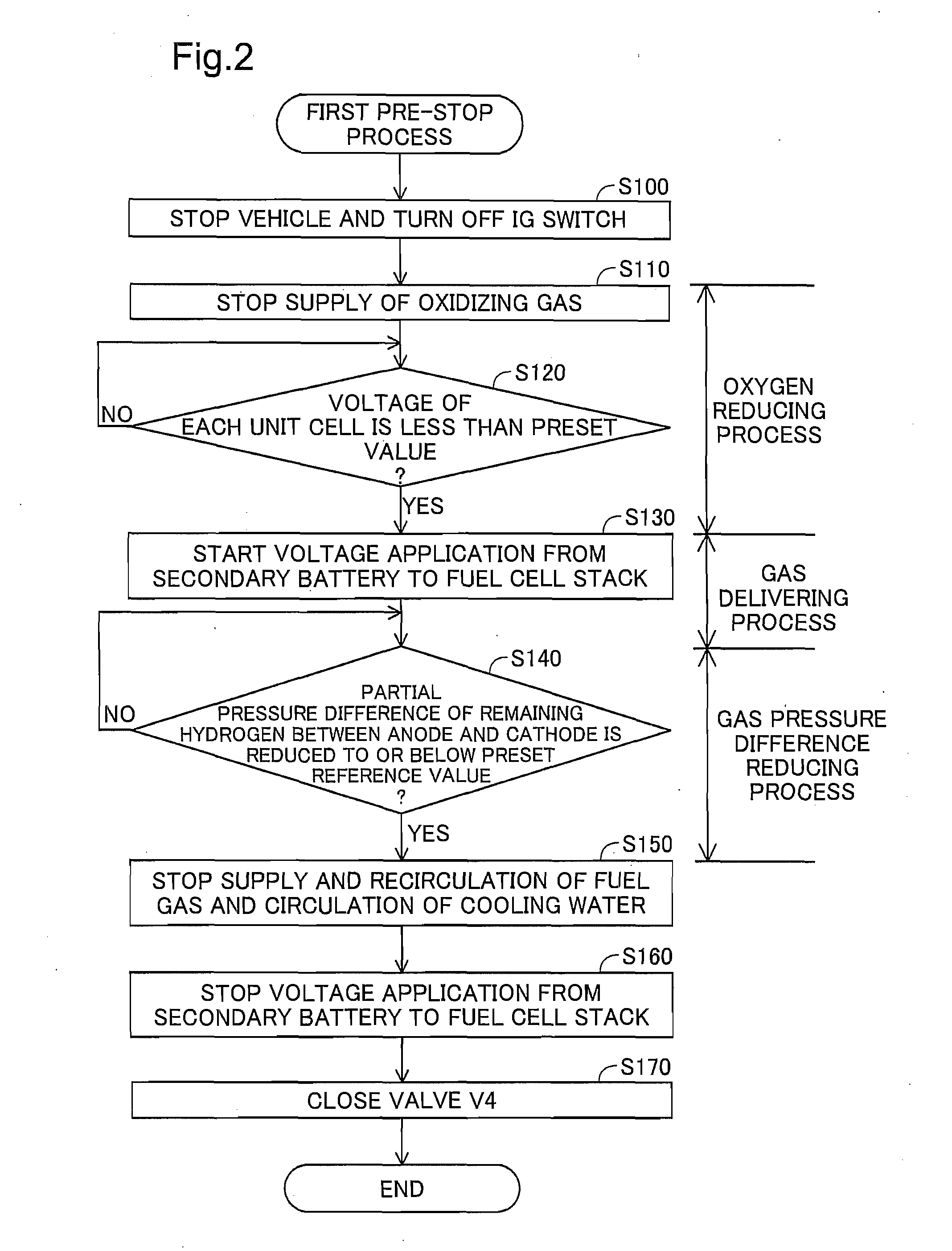
[0169]The processing of step S140a may be replaced with step S140 of the first pre-stop process (FIG. 2). Such modified procedure also enables reduction of the variation of the cathode total pressure. Reducing the partial pressure difference of at least hydrogen, which has the higher permeation rate through the electrolyte membrane at a specific partial pressure difference than nitrogen, to or below the preset reference value reduces the variation of the cathode total pressure and prevents negative pressure in the cathode. This prevents introduction of the air from outside the fuel cell stack 10 into the cathode.
B-3-2. Second Modification
[0170]The second fuel cell stack 12, the load connector 48 and the external DC power source 210 may be omitted, as long as the exhaust gas return pipe 52 is provided to be branched off from the oxidizing gas exhaust pipe 33 and to be connected with the oxidizing gas supply pipe 32. Acco...
third embodiment
C-3. Modifications of Third Embodiment
C-3-1. First Modification
[0186]The processing of step S102 may be omitted. Such modified procedure still enables at least reduction of the variation of the cathode total pressure and prevention of the oxidation of the cathode component material. The secondary battery 200 and the DC-DC converter 300 may be omitted. Such modified structure enables the gas delivering process.
C-3-2. Second Modification
[0187]Like the first modification of the third second embodiment, the processing of step S140a may be replaced with step S140 (FIG. 2). Like the second modification of the first embodiment, the valve V4 may not be provided in the oxidizing gas exhaust pipe 33. Like the third modification of the first embodiment, pure oxygen may be used as the oxidizing gas.
C-3-3. Third Modification
[0188]The processing of step S104 (FIG. 7) may be modified to start power generation with setting the stoichiometric ratio of the fuel gas (hereinafter also called “hydrogen ...
PUM
| Property | Measurement | Unit |
|---|---|---|
| temperature | aaaaa | aaaaa |
| unit cell voltage | aaaaa | aaaaa |
| unit cell voltage | aaaaa | aaaaa |
Abstract
Description
Claims
Application Information