System to remove Dissolved Gases Selectively from Liquids

a liquid removal and dissolved gas technology, applied in liquid degasification, separation processes, water/sewage treatment by degassing, etc., can solve the problems of compromising the low oxygen concentration needed for many semiconductor applications, reducing the efficiency of current membrane based vacuum degas systems, and reducing the amount of silicon dioxide removed. , the effect of low maintenance effor

Active Publication Date: 2012-11-08
MKS INSTR INC
View PDF5 Cites 28 Cited by
  • Summary
  • Abstract
  • Description
  • Claims
  • Application Information

AI Technical Summary

Benefits of technology

[0034]Some advantages of the invention are a higher lifetime and a low effort for maintenance or no effort for maintenance (e.g., maintenance free), as compared to conventional systems. For example, current systems can require that membrane contactors be exchanged up to every two years. Further advantages of the invention include a low consumption of inert gas, lower cost and a small size. For example, reduction of inert gas consumption by a factor of 5 can be achieved.
[0035]Even further advantages are that inert gases that exit the first contactor can be used as a nitrogen blanket for the degassing system, thus reducing back diffusion of oxygen through the contactor walls or the piping into the liquid. Even further advantages are that evaporation of the liquid source can be avoided.

Problems solved by technology

Oxygen in etching liquid may oxide further silicon, which can result in removal of more silicon dioxide than a desired amount.
Current membrane based vacuum degas systems have a limited lifetime, thus they can need to be replaced every few years.
The DI-water piping can increase the amount of oxygen concentration in the DI-water, thus compromise the low level of oxygen concentration necessary for many semiconductor applications.
The diffusion of oxygen through the piping can also limit process stability, as the oxygen concentration in the DI-water depends on the overall residence time of the water in the piping.

Method used


Image

  • System to remove Dissolved Gases Selectively from Liquids
  • System to remove Dissolved Gases Selectively from Liquids
  • System to remove Dissolved Gases Selectively from Liquids

Examples


Embodiment Construction

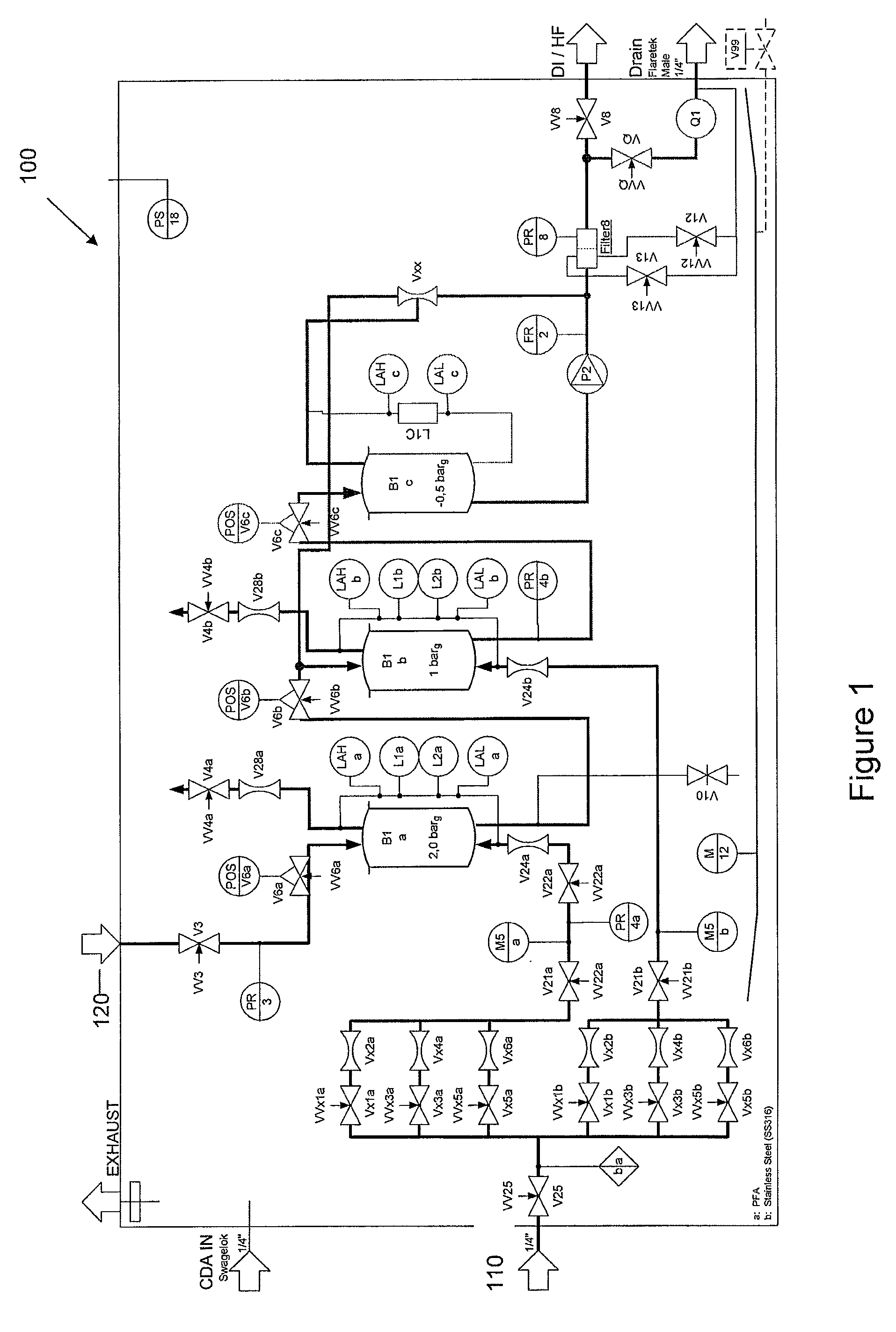
[0045]In general overview, a system to purge gases selectively from liquids can include two or more contactors. Each contactor purges a portion of the gas. The system can include a boost pump in order to boost the pressure of the outlet liquid of the last contactor. The system can also include a liquid jet vacuum pump, which can use a part of the pressurized outlet liquid as a motivating fluid. In a two contactor system, with a liquid jet vacuum pump, the first contactor runs at a higher pressure than the second contactor, and the liquid jet vacuum pump can recycle gas and liquid from the second contactor back into the first contactor, thus behaving as a vacuum source.

[0046]FIG. 1 is a block diagram of an exemplary embodiment of a system 100 to purge gases selectively from liquids. The system 100 has two contactors B1a and B1b to purge unwanted gas. A liquid inlet 120 (i.e., a liquid source) is in fluid communication with a first contactor B1a via controlled valves V3 and V6a to sup...


PUM

PropertyMeasurementUnit
inertaaaaaaaaaa
permeabilityaaaaaaaaaa
vacuum levelaaaaaaaaaa

Abstract

A system to purge dissolved gases selectively from liquids can include a first contactor having two first contactor inlets and two first contactor outlets. The first contactor can receive liquid from a liquid source at a first inlet of the first contactor and an inert gas source at a second inlet of the first contactor, the inert gas can purge a first portion of gas from the liquid source. The first portion of purged gas exits the first contactor at a first outlet of the first contactor. The second contactor can receive input from the second outlet of the first contactor and the inert gas, the inert gas purges a second portion of the gas from the liquid source. The second portion of purged gas can exit the second contactor at a first outlet of the second contactor.

Description

CROSS REFERENCE TO RELATED APPLICATION[0001]This application claims the benefit of and priority to U.S. Provisional Patent Application No. 61 / 452,905, filed Mar. 15, 2011, the entire disclosure of which is incorporated herein by reference.FIELD OF THE INVENTION[0002]In general, the invention relates to devices, systems and methods employed in wet cleaning semiconductor devices. In particular, the invention relates to a system that can purge unwanted gases from liquids.BACKGROUND OF THE INVENTION[0003]Microelectronics chips such as integrated circuits are made from comparatively large wafers of semiconductor material. This process typically involves multiple successive steps including the following: generation of an etch mask photolithographically; etching of a layer of material as defined by the mask; removal of the photolithographic mask through some combination of wet and dry chemical techniques; removal of oxide layers prior to further processing; deposition of layers of material...

Claims


Application Information

Patent Timeline
Patent Type & Authority Applications(United States)
IPC IPC(8): B01D19/00
CPCB01D19/0005B01D19/0031B01D19/0036B01D19/0063B01D19/0068C02F2209/40C02F2103/04C02F2209/225C02F2209/245C02F2209/38C02F1/20B01D19/00
Inventor BRAMMER, ULRICHSEIWERT, JOHANNESGOTTSCHALK, CHRISTIANE
Owner MKS INSTR INC
Why Eureka
Try Eureka