

Fixed-array anisotropic conductive film using surface modified conductive particles
- Summary
- Abstract
- Description
- Claims
- Application Information
AI Technical Summary
Benefits of technology
Problems solved by technology
Method used
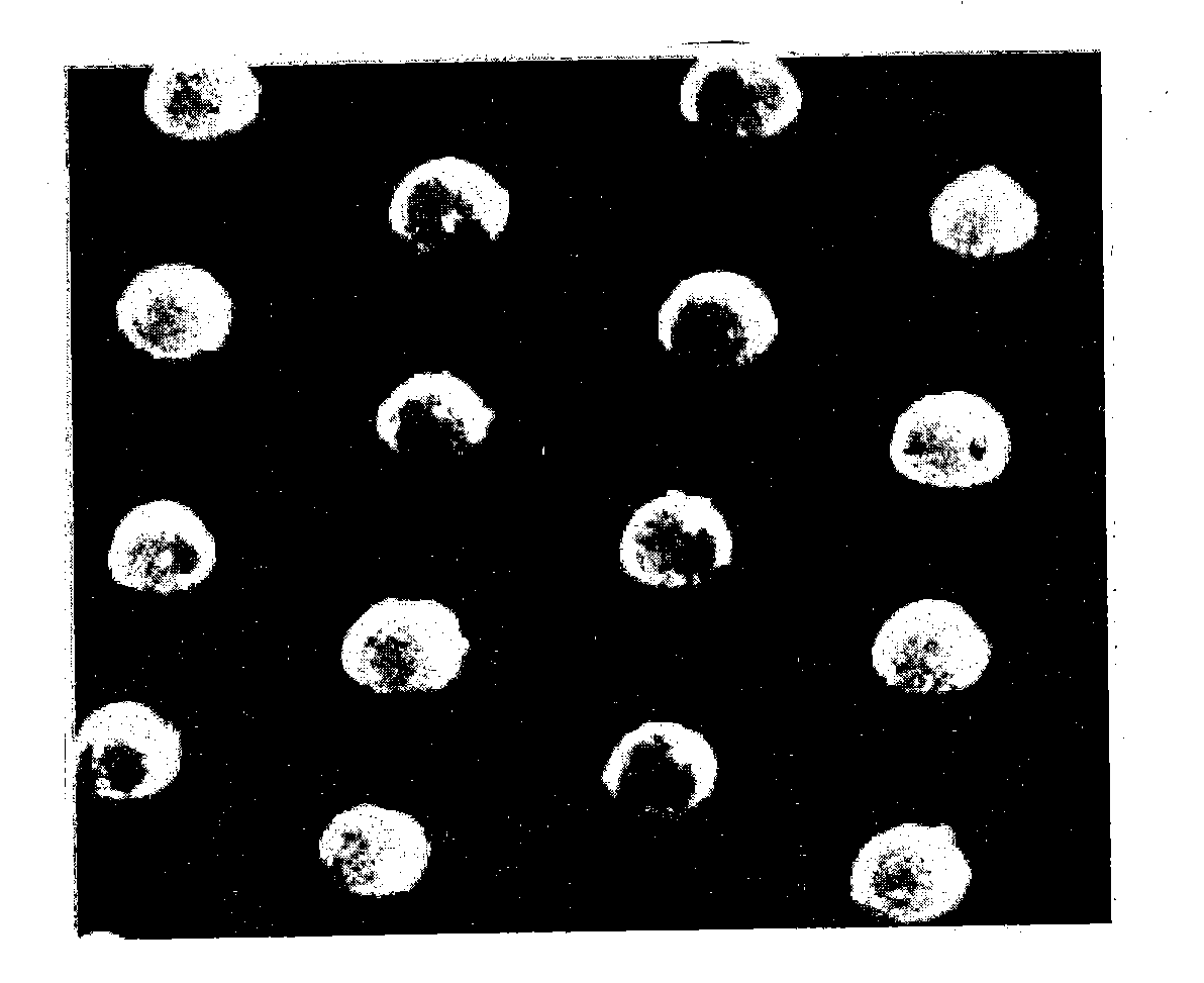
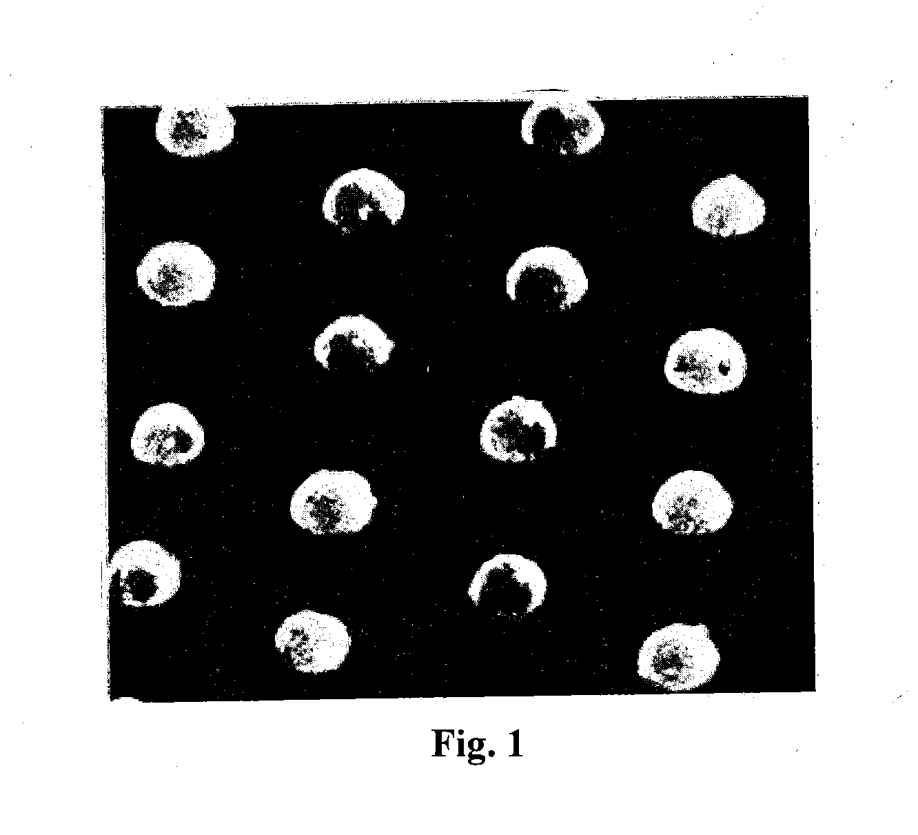
Image

Examples
example 1
Preparation of SCA Treated Conductive Particle
[0045]Weigh 12 g of a Au particle into a 1 L reaction kettle. Add 226 g of Isopropyl Alcohol (IPA) to provide about 5wt % of Au in IPA. Add 12 g of gamma-mercapto-propyltrimethoxysilane into the Au dispersion in IPA. Close the kettle and apply ultrasonication for 30 min. After completed, the mixture was stirring 12˜24 hours under room temperature. The Au particle was allowed to settle and rinsed to remove excess solvent. The rinsing process is repeated until no unreacted coupling agent in the rinsing solvent can be detected by thin layer chromatography. Essentially, the entire surface of the particles was coated with the coupling agent (100% coverage).
Preparation of the Adhesive Layer
[0046]13 grams of phenoxy resin PKFE (from InChem Rez), 2 grams of PKCP-80 (from InChem Rez) and 1 gram of M52N (from Arkema, Philadelphia) were added to 40 grams of ethyl acetate. The solution was heated at 70° C. and mixed with stirring until all the pheno...
example 2
Effect of Particle Surface Treatment on Contact Resistance
[0048]Four 12 μm ACF samples were prepared using commercially available non-spiky Au conductive particles and spiky Au conductive particles. One set of samples was treated with the coupling agent described in Example 1. The other set was not. The particle densities of these ACFs are in the range of 6,000 pcs / mm2. The particle diameter was 3.2 μm and they were embedded to a depth of about 2.2 μm such that about 1 μm of the surface was exposed. After bonding, contact resistance was measured via two point probe method using Keithley 2400 Sourcemeter and shown in Table 1 below. There is no observable difference on contact resistance due to particle type or particles surface treatment. It is evident that the surface treatment did not cause any detrimental effect on the contact conductivity or resistivity of the bonded electrodes.
TABLE 1Effect of Particle Type and SurfaceTreatment on Contact ResistanceContact ResistanceParticle Typ...
example 3
Effect of Particle Surface Treatment on Insulation Resistance
[0049]Table 2 shows the effect of particle surface treatment on insulation resistance. ACF samples were prepared using an adhesive of about 12 μm thickness and spiky Au particles with or without surface treatment as described in Example 1. These particles were pre-baked at 80° C. for 16 hours before being coated onto the adhesive film. Constant voltage of 25 volts was applied to these bonded samples to measure insulation resistance of the non-contact area using an Agilent 4339B High Resistance Meter. The results are shown in Table 2.
[0050]From Table 2, insulation resistance of bonded ACF samples is in the same order of magnitude for both ACF's with or without surface-treated particles. There was no observable effect of particle surface treatment on insulation resistance even after the samples were aged 366 hours at 85° C. and 85% RH.
TABLE 2Effect of Particle Surface Treatment on Insulation ResistanceInsulation Resistance (...
PUM
| Property | Measurement | Unit |
|---|---|---|
| Fraction | aaaaa | aaaaa |
| Fraction | aaaaa | aaaaa |
| Fraction | aaaaa | aaaaa |
Abstract
Description
Claims
Application Information