Crosslinking polymer-supported porous film for battery separator and method for producing battery using the same

a technology of polymer-supported porous film and battery separator, which is applied in the direction of cell components, final product manufacturing, sustainable manufacturing/processing, etc., can solve the problems of deteriorating battery performance, increasing the internal resistance of the battery, and partially extending the distance between the electrodes, etc., to achieve low internal resistance, high-rate performance, and sufficient adhesiveness

Inactive Publication Date: 2012-11-29
NITTO DENKO CORP
View PDF6 Cites 0 Cited by
  • Summary
  • Abstract
  • Description
  • Claims
  • Application Information

AI Technical Summary

Benefits of technology

[0011]Accordingly, one object of the present invention is to provide a surface-treated porous film having a polymer supported thereon, for a battery separator, which can suitably be used for the production of a battery having sufficient adhesiveness between electrodes and a separator, low internal resistance and high-rate performance.

Problems solved by technology

Because face pressure for maintaining the electric connection between the separator and the electrodes cannot sufficiently be applied to the face of the electrodes, the distance between the electrodes partially gets longer over time due to the expansion and shrinkage of electrode active substances during the charge or discharge of the battery.
Thus, the internal resistance of the battery increases, involving deterioration of the battery performance.
Additionally, the occurrence of resistance variation inside the battery also disadvantageously deteriorates the battery performance.
In the case of producing a sheet-like battery of a large area, the distance between the electrodes cannot be fixed, so that satisfactory battery performance cannot be obtained due to the resulting resistance variation inside the battery.
Further, because the amount of the electrolyte solution relative to the adhesive resin cannot increase, the internal resistance of the resulting batteries is high, so that satisfactory cycle performance and high-rate discharge performance cannot be obtained, which is disadvantageous.

Method used


Image

  • Crosslinking polymer-supported porous film for battery separator and method for producing battery using the same
  • Crosslinking polymer-supported porous film for battery separator and method for producing battery using the same
  • Crosslinking polymer-supported porous film for battery separator and method for producing battery using the same

Examples


reference example 1

Preparation of Electrode Sheet

[0060]85 Parts of lithium cobalt oxide as a positive electrode active material (Cell Seed C-10 manufactured by Nippon Chemical Industrial Co., Ltd.), 10 parts of acetylene black as a conductive auxiliary agent (Denka Black manufactured by Denki Kagaku Kogyo Kabushiki Kaisha) and 5 parts of a vinylidene fluoride resin as a binder (KF polymer L #1120 manufactured by Kureha Chemical Industry, Co., Ltd.) were mixed together. Using N-methyl-2-pyrrolidone, a slurry of the resulting mixture was prepared so as to have a solid concentration of 15% by weight. The slurry was applied to one side of a 20 μm thick aluminum foil (current collector) at a build-up of 200 μm, dried at 80° C. for 1 hour and then at 120° C. for 2 hours, and pressed with a roll press, to prepare a positive electrode sheet having an active material layer thickness of 100 μm.

[0061]80 Parts of mesocarbon microbeads as a negative electrode active material (MCMB 6-28 manufactured by Osaka Gas Ch...

production example 1

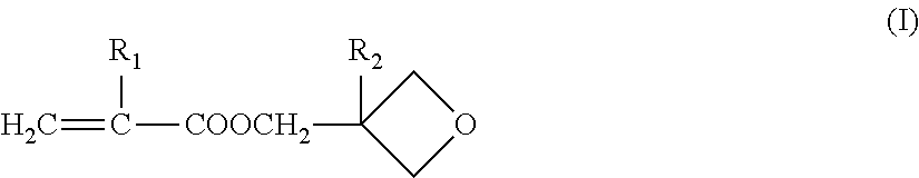
[0064]Production of 3-oxetanyl Group-Containing Crosslinking Polymer A (Weight Average Molecular Weight: 518,000 and Content of 3-oxetanyl Group-Containing Monomer Content: 25% by Weight)

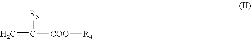
[0065]60.0 g of methyl methacrylate, 20.0 g of 3-ethyl-3-oxetanylmethyl methacrylate, 158.0 g of ethyl acetate and 0.16 g of N,N′-azobisisobutyronitrile were placed in a 500 ml three-necked flask equipped with a reflux condenser, and mixed for 30 minutes under stirring while introducing nitrogen gas. Radical polymerization was initiated at 60° C. When about 2 hours passed, the viscosity of the reaction mixture began to increase. The reaction mixture was further polymerized for additional 8 hours. The reaction mixture was cooled to about 10° C., and 0.16 g of azobisbutyronitrile was added thereto. The resulting mixture was again heated to 70° C., and polymerization was conducted for 8 hours.

[0066]After completion of the reaction, the reaction mixture was cooled to about 40° C., and 295 g of ethyl ace...

production example 2

[0068]Production of 3-oxetanyl Group-Containing Crosslinking Polymer B (Weight Average Molecular Weight: 253,000 and Content of 3-oxetanyl Group-Containing Monomer Component: 15% by Weight)

[0069]In the same manner as in the Production Example 1, 68.0 g of methyl methacrylate, 12.0 g of 3-ethyl-3-oxetanylmethyl methacrylate, 158.0 g of ethyl acetate and 0.15 g of N,N′-azobisisobutyronitrile were placed in a 500 ml three-necked flask equipped with a reflux condenser, and mixed for 30 minutes under stirring while introducing nitrogen gas. Radical polymerization was initiated at 70° C. When about 1.5 hours passed, the viscosity of the reaction mixture began to increase. The reaction mixture was further polymerized for additional 8 hours. The reaction mixture was cooled to about 40° C., and 0.15 g of azobisbutyronitrile was added thereto. The resulting mixture was again heated to 70° C., and polymerization was conducted for 8 hours.

[0070]After completion of the reaction, the reaction mix...


PUM

PropertyMeasurementUnit
thicknessaaaaaaaaaa
thicknessaaaaaaaaaa
porosityaaaaaaaaaa

Abstract

The method for producing a battery, includes the steps of: laminating electrodes on the crosslinking polymer-supported porous film to prepare a laminate of crosslinking polymer-supported porous film / electrodes; placing the laminate in a battery container; and pouring an electrolyte solution containing a cation polymerization catalyst in the battery container to induce cation polymerization and crosslinking of the crosslinking polymer, thereby at least partially gelling the electrolyte solution to adhere the porous film and the electrodes.

Description

[0001]This application is a divisional of application Ser. No. 10 / 724,882, which claims priority from JP 2002-350223 filed Dec. 2, 2002, the contents of all of which are incorporated herein by reference in their entirety.FIELD OF THE INVENTION[0002]The present invention relates to a crosslinking polymer-supported porous film for battery separator, comprising a porous film substrate having supported thereon a crosslinking polymer having plural cation-polymerizable functional groups in the molecule, and a method for producing a battery by adhering electrodes to a separator using the crosslinking polymer-supported porous film.DESCRIPTION OF THE RELATED ART[0003]In recent years, lithium ion secondary batteries with high energy density have been widely used as a power source of small-type hand-held electronic devices such as cell phone and laptop personal computer. Such lithium ion secondary batteries are produced by a process including a step of laminating or winding, for example, a pol...

Claims


Application Information

Patent Timeline
Patent Type & Authority Applications(United States)
IPC IPC(8): H01M10/04B32B27/30C08J5/18H01M10/05H01M10/0525H01M10/0565H01M10/058H01M50/406H01M50/417H01M50/42H01M50/449H01M50/491
CPCB32B27/30H01M2/145H01M2/1653H01M2/1673H01M2/1686Y10T29/49112H01M10/0565H01M2300/0082H01M2300/0085Y02E60/122H01M10/052Y02P70/50Y02E60/10H01M50/46H01M50/449H01M50/417H01M50/406H01M50/491H01M50/42C08J5/18B32B2323/10B32B2323/04B32B2305/026B32B27/32B32B2379/08B32B27/08B32B2327/18
Inventor UETANI, YOSHIHIROKII, KEISUKENISHIKAWA, SATOSHI
Owner NITTO DENKO CORP
Why Eureka
Try Eureka