Solar cell and solar cell module

a solar cell and solar cell technology, applied in the field of solar cell and solar cell module, can solve the problems of high silicon substrate production cost, rise in production cost, and inability to solve the problems described above, so as to reduce the time required for introducing electrolyte solution, reduce the pressure efficiently, and facilitate the effect of sufficient electrolyte solution permeation all over the solar cell

Inactive Publication Date: 2012-11-29
SHARP KK
View PDF0 Cites 4 Cited by
  • Summary
  • Abstract
  • Description
  • Claims
  • Application Information

AI Technical Summary

Benefits of technology

[0021]According to the present invention, since it becomes possible to reduce the internal pressure of the solar battery cell thorough the second opening provided in addition to the first opening, the pressure can be reduced efficiently. Further, since it becomes possible to inject an electrolyte solution all over the solar battery cell through the second opening provided in addition to the first opening, sufficient electrolyte solution permeation all over the solar cell is facilitated, and the time required for injecting the electrolyte solution can be reduced.

Problems solved by technology

However, the former faces the problem of high production cost of the silicon substrate, and the latter faces the problem of rise in the production cost because it is required to use many kinds of gases for semiconductor production and a complicated apparatus.
Therefore, in any solar cells, efforts for improving the efficiency of photoelectric conversion for reducing the cost per electric generation output are continued, however, the problems as described above have not been solved.
However, the basic structure of the pigment-sensitized solar cell described in PTL 1 is a cell form where an electrolyte solution is injected between two opposite glass substrates having transparent conductive films, and it is difficult to be applied to a solar cell having such a large area as 1 m square, although trial manufacture of a solar cell having a small area is possible.
As a result, a problem arises that FF (fill factor) in the current voltage characteristics at the time of photoelectric conversion decreases, and the photoelectric conversion efficiency deteriorates.
However, when a pigment-sensitized solar cell module where a plurality of elongated strip-like pigment-sensitized solar battery cells are arranged in a stripe form and connected in series as described in PTL 2 or PTL 3 is fabricated, this method for injecting an electrolyte solution has such a big problem as will be mentioned below.
Therefore, in the case of injection of an electrolyte solution from an end part, a substantial time is required, and operation efficiency of cell fabrication deteriorates.
Further, in the case of injection of an electrolyte solution from an end part, injection of the electrolyte solution into the middle of the cell is insufficient, which may lead to deterioration in conversion efficiency.

Method used


Image

  • Solar cell and solar cell module
  • Solar cell and solar cell module
  • Solar cell and solar cell module

Examples


first embodiment

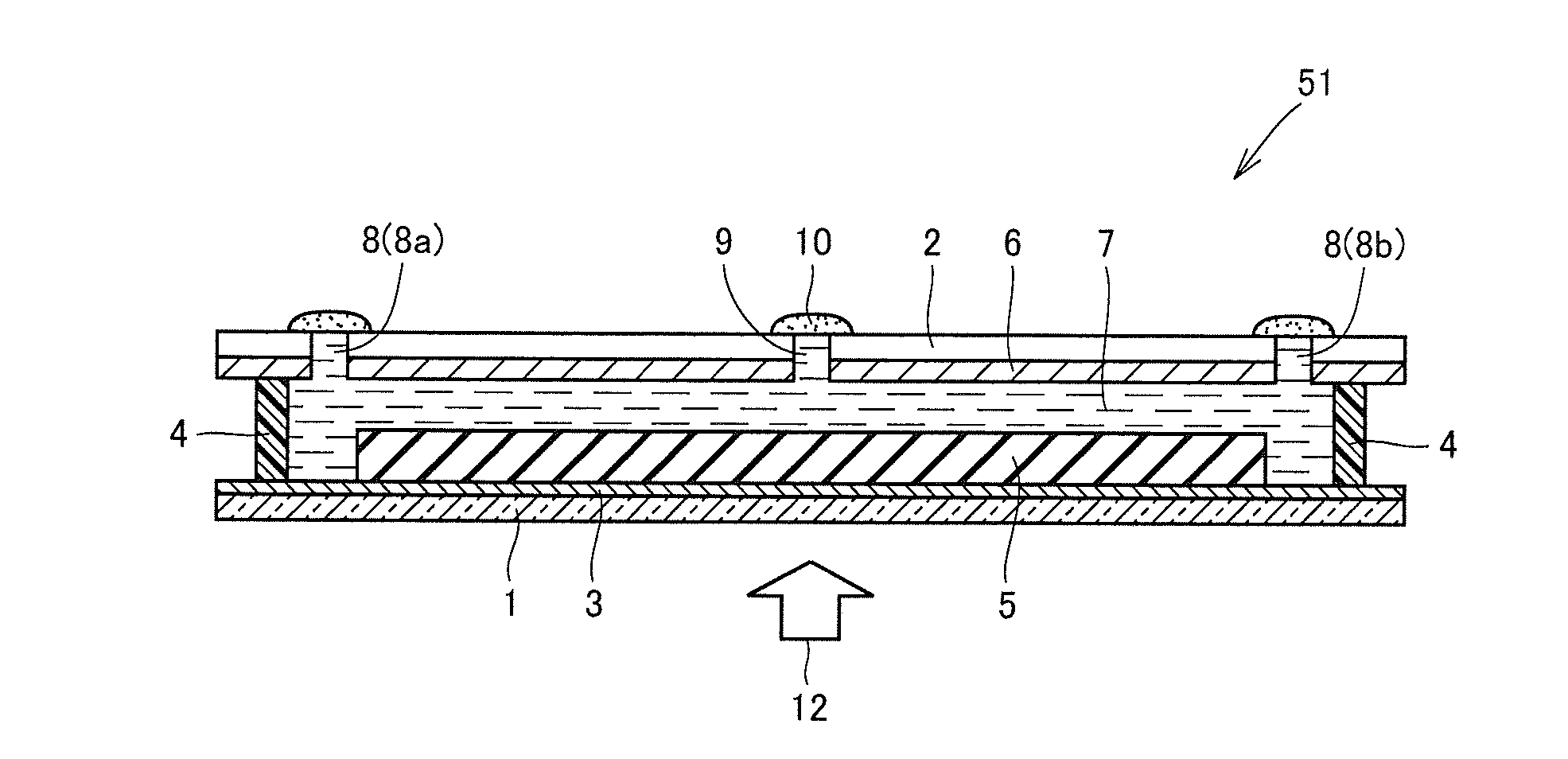
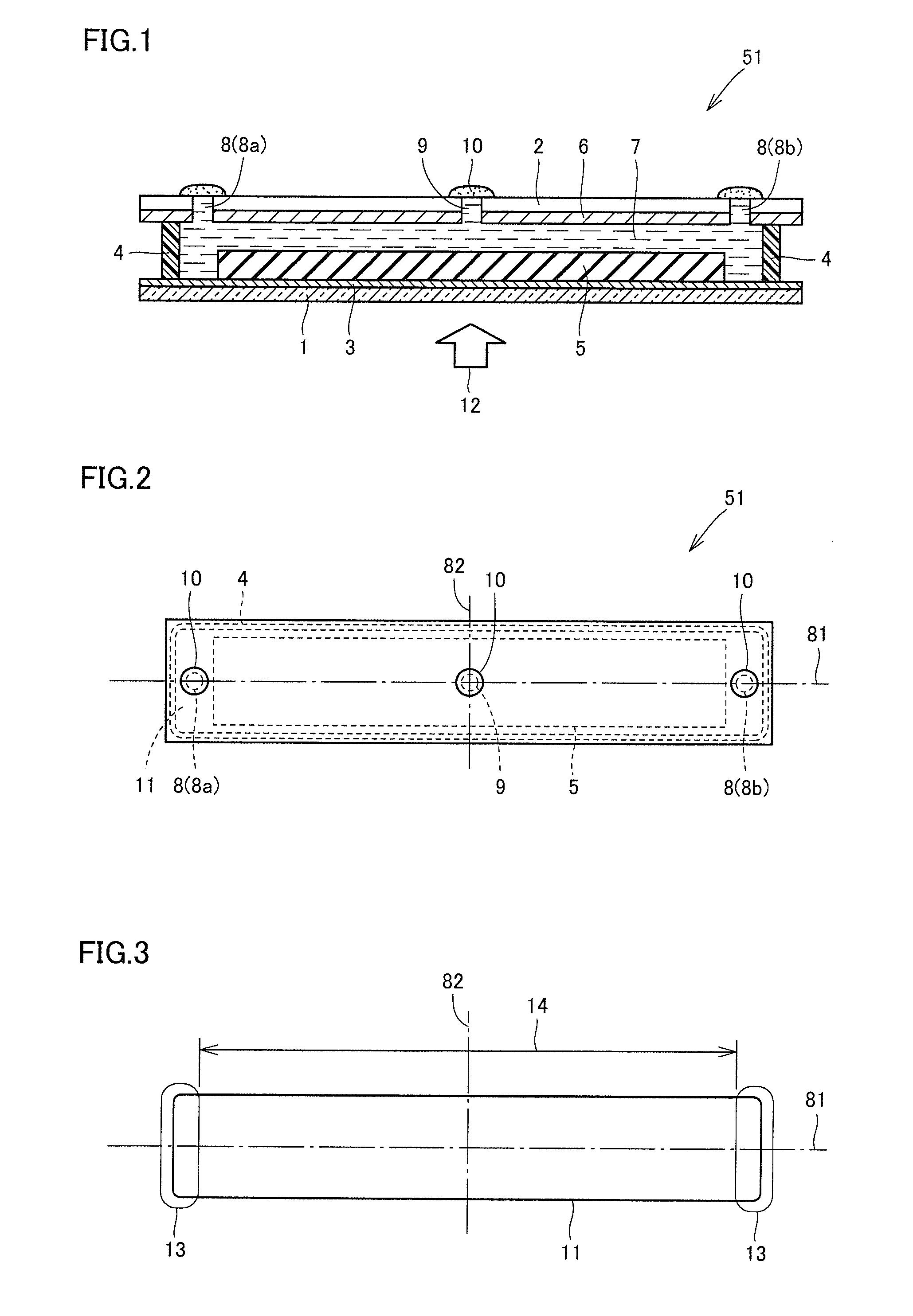
[0039]Referring to FIG. 1 and FIG. 2, a solar cell in a first embodiment according to the present invention will be described. A section view of the solar cell in the present embodiment is shown in FIG. 1, and a plan view Of the solar cell is shown in FIG. 2, A solar cell 51 is a wet solar cell. Solar cell 51 includes a light transmissive substrate 1, a supporting substrate 2 disposed parallel with light transmissive substrate 1, a photoelectric conversion part 5 and a counter electrode 6 that are disposed between light transmissive substrate 1 and supporting substrate 2 in such a manner that they are spaced from each other, an electrolyte part 7 disposed between light transmissive substrate 1 and supporting substrate 2 while being in contact with photoelectric conversion part 5 and counter electrode 6, and a sealing part 4 that surrounds and seals electrolyte part 7 in such a manner that electrolyte part 7 is retained within an electrolyte disposition region 11 that is a region def...

second embodiment

[0107]Referring to FIG. 10 and FIG. 11, a solar cell module in a second embodiment according to the present invention will be described. The solar cell module according to the present invention is a solar cell module including the configuration where a plurality of solar cells including at least one solar cell are connected as is mentioned above. That is, not all of the connected plural solar cells need to be the solar cell as described above, and it suffices that at least one of the solar cells is the solar cell as described above. All of the solar cells may be the solar cell as described above. The connected solar cells are electrically connected in series.

[0108]FIG. 10 schematically shows a solar cell module 501 in the present embodiment.

[0109]In configuring solar cell module 501, a plurality of strip-like solar cells 51 are assembled, and arranged in parallel so that the long sides of individual solar cells 51 mutually contact with each other and connected. FIG. 11 is a section ...

examples 1 to 5

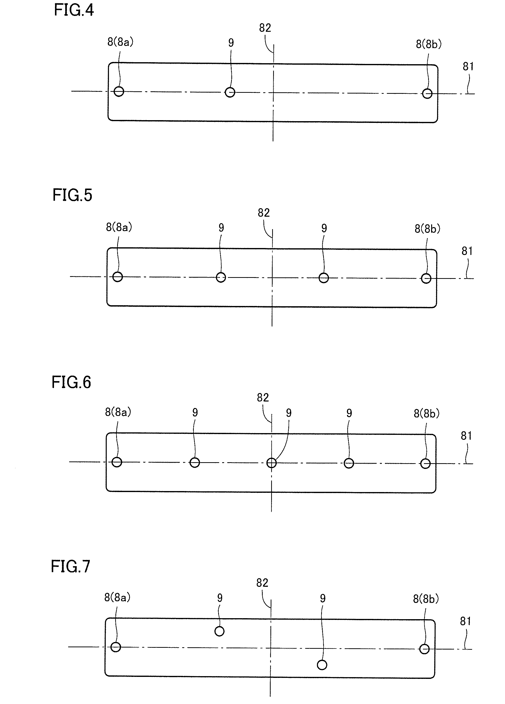
[0114]As a solar cell according to the present invention, a pigment-sensitized solar cell was fabricated. The production method will be concretely shown below. The pigment-sensitized solar cell has a structure shown in FIG. 1 and FIG. 2. However, the number of second openings 9 is not limited to that shown in FIG. 1 and FIG. 2. In examples, for the purpose of comparison, plural kinds of solar cells were fabricated while the arrangement density of second openings 9, namely the value of N as will be described later was varied.

[0115]First, as a support formed with the conductive layer, two glass substrates with a SnO2 film available from Nippon Sheet Glass Co., Ltd. were prepared. This is a glass substrate formed with a SnO2 film which is a transparent conductive layer on one face. Of these two substrates, one is to serve as light transmissive substrate 1 and transparent conductive film 3 in FIG. 1, and the other is to serve as supporting substrate 2 and counter electrode 6. The combin...


PUM


Abstract

A solar cell includes a light transmissive substrate, a supporting substrate, a photoelectric conversion part and a counter electrode disposed between the light transmissive substrate and the supporting substrate in such a manner that they are spaced from each other; an electrolyte part disposed between the light transmissive substrate and the supporting substrate while being in contact with the photoelectric conversion part and the counter electrode, and a sealing part that surrounds and seals the electrolyte part in such a manner that the electrolyte part is retained within an electrolyte disposition region. First openings that make the electrolyte part communicate with the outside are provided at least in one end part in the electrolyte disposition region, and at least one second opening that makes the electrolyte part communicate with the outside is provided in the middle part in the electrolyte disposition region. The first and second openings are sealed.

Description

TECHNICAL FIELD[0001]The present invention relates to a solar cell and a solar cell module.BACKGROUND ART[0002]As energy sources that are alternative to fossil fuels, batteries capable of converting sunlight into electric power, namely solar cells are focused on. At present, a solar cell using a crystalline silicon substrate and a thin-film silicon solar cell are partly coming into practical use. However, the former faces the problem of high production cost of the silicon substrate, and the latter faces the problem of rise in the production cost because it is required to use many kinds of gases for semiconductor production and a complicated apparatus. Therefore, in any solar cells, efforts for improving the efficiency of photoelectric conversion for reducing the cost per electric generation output are continued, however, the problems as described above have not been solved.[0003]As a new type of solar cell, a wet solar cell applying photo-induced electron transfer of a metal complex...

Claims


Application Information

Patent Timeline
Patent Type & Authority Applications(United States)
IPC IPC(8): H01L31/042H01L31/0203H01L51/44
CPCH01G9/2031H01G9/2059H01M14/005H01G9/2081Y02E10/542H01G9/2068
Inventor MIURA, YOSHIYUKIKOMIYA, RYOICHIFUKUI, ATSUSHIYAMANAKA, RYOHSUKE
Owner SHARP KK
Why Eureka
Try Eureka