Silicon-air batteries

Inactive Publication Date: 2012-11-29
PENN STATE RES FOUND +1
View PDF6 Cites 10 Cited by
  • Summary
  • Abstract
  • Description
  • Claims
  • Application Information

AI Technical Summary

Benefits of technology

[0045]In some embodiments, the battery presented herein furth

Problems solved by technology

However, these electrochemical cell devices are still far from mass production due to multiple practical limitations.
However, high open circuit corrosion rates lead to the consumption of the Al metal anode without any usable power output.
Although theoretically high energy density is expected from a lithium-air cell system, nontrivial challenges associated with a practical lithium-air cell exist.
For example, lithium suffers from severe corrosion in alkaline electrolytes and safety concerns are still unresolved with aqueous systems.
In addition, lithium-air cells are sensitive to anode passivation due to air/moistu

Method used


Image

  • Silicon-air batteries
  • Silicon-air batteries
  • Silicon-air batteries

Examples


example 1

Half-Cell Analysis of Silicon-Air Battery

[0178]The sensitivity of silicon to KOH is a well known fact which is employed in the silicon industry to etch silicon. Silicon etching rate is measured to be in the order of tens of nm per minute and therefore, high rates of self discharge processes are expected from silicon-air batteries using KOH as the electrolyte. However, silicon-air batteries using the intuitive electrolyte KOH showed rapidly decreasing output due to extreme fast corrosion process of silicon in alkaline solutions.

[0179]To overcome the problems associated with aqueous alkaline electrolytes, non-aqueous room temperature ionic liquids RTIL were used as electrolytes in the following examples. Specifically, EMI.(HF)2.3F, an exemplary RTIL, was chosen as an alternative electrolyte due to its special features and due to the anodic features.

[0180]RTILs based on 1-Ethyl-3-methyl-imidazolium (EMI) cation exhibit low viscosity and high conductivity. The synthesis of EMI.(HF)2.3F ...

example 2

Galvanostatic Discharge Behavior

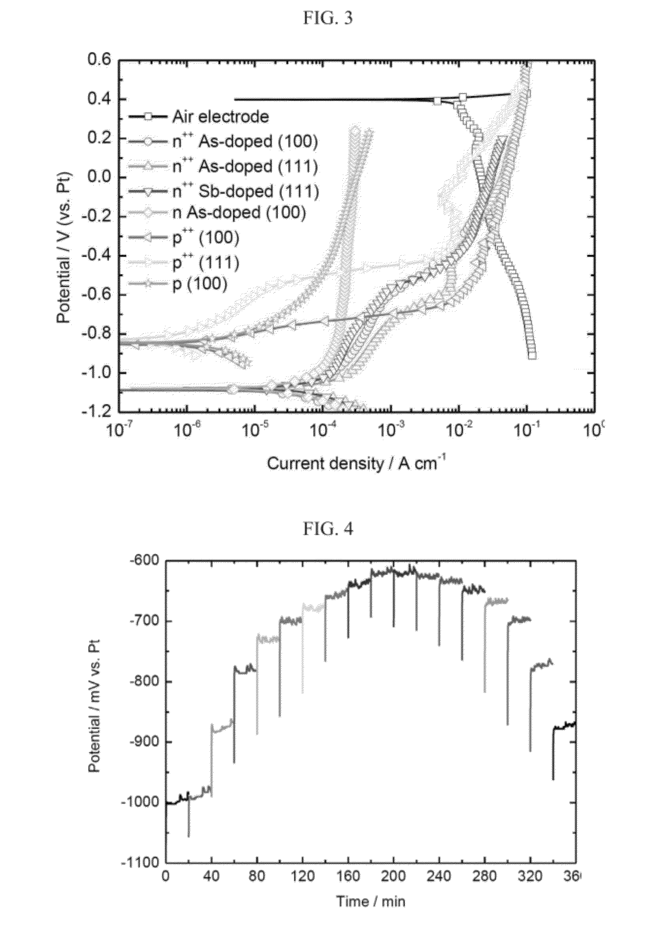
[0192]The galvanostatic discharge behavior of a silicon-air battery was studied by polarization of the working electrode against a Pt counter electrode at different current densities, resulting in up and down staircase curves, as presented in FIG. 4.

[0193]FIG. 4 presents the galvanostatic polarization curve as measured for an exemplary silicon-air battery according to the present invention, using a silicon [100] of anode heavily As-doped n-type (n++) and EMI.(HF)2.3F electrolyte (corresponding to the red curve having the circle symbol in FIG. 3), and current density from 100 μA per cm−2 to 1000 μA per cm−2 and back to 100 μA per cm−2, in 100 μA per cm−2 intervals, each for 20 minutes.

[0194]As can be seen in FIG. 4, the obtained half-cell potential value is more positive as the current density increases. However, frequent fluctuations are observed in each step of the 20 minutes constant current polarization. The frequency of these fluctuations depends ...

example 3

Silicon-Air Battery Discharge Performance

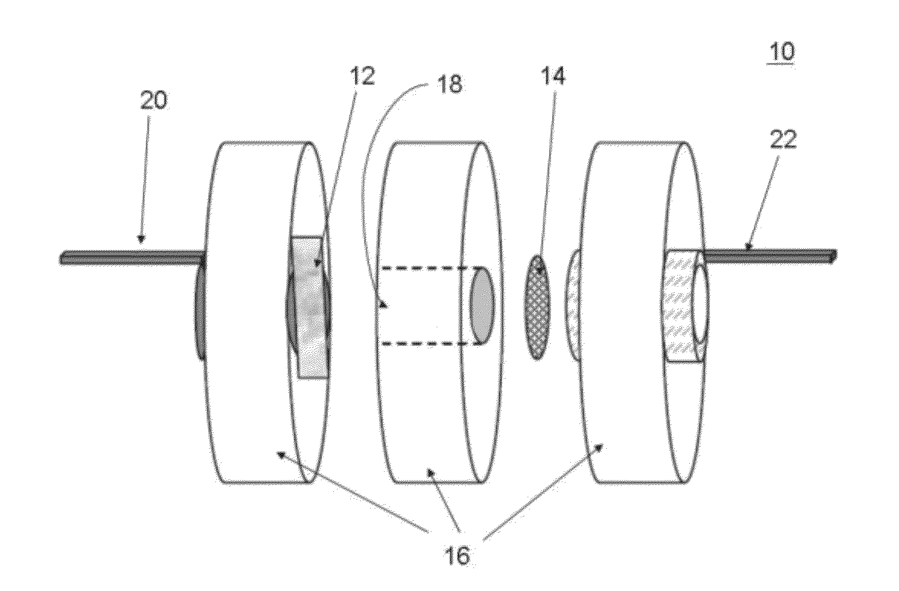
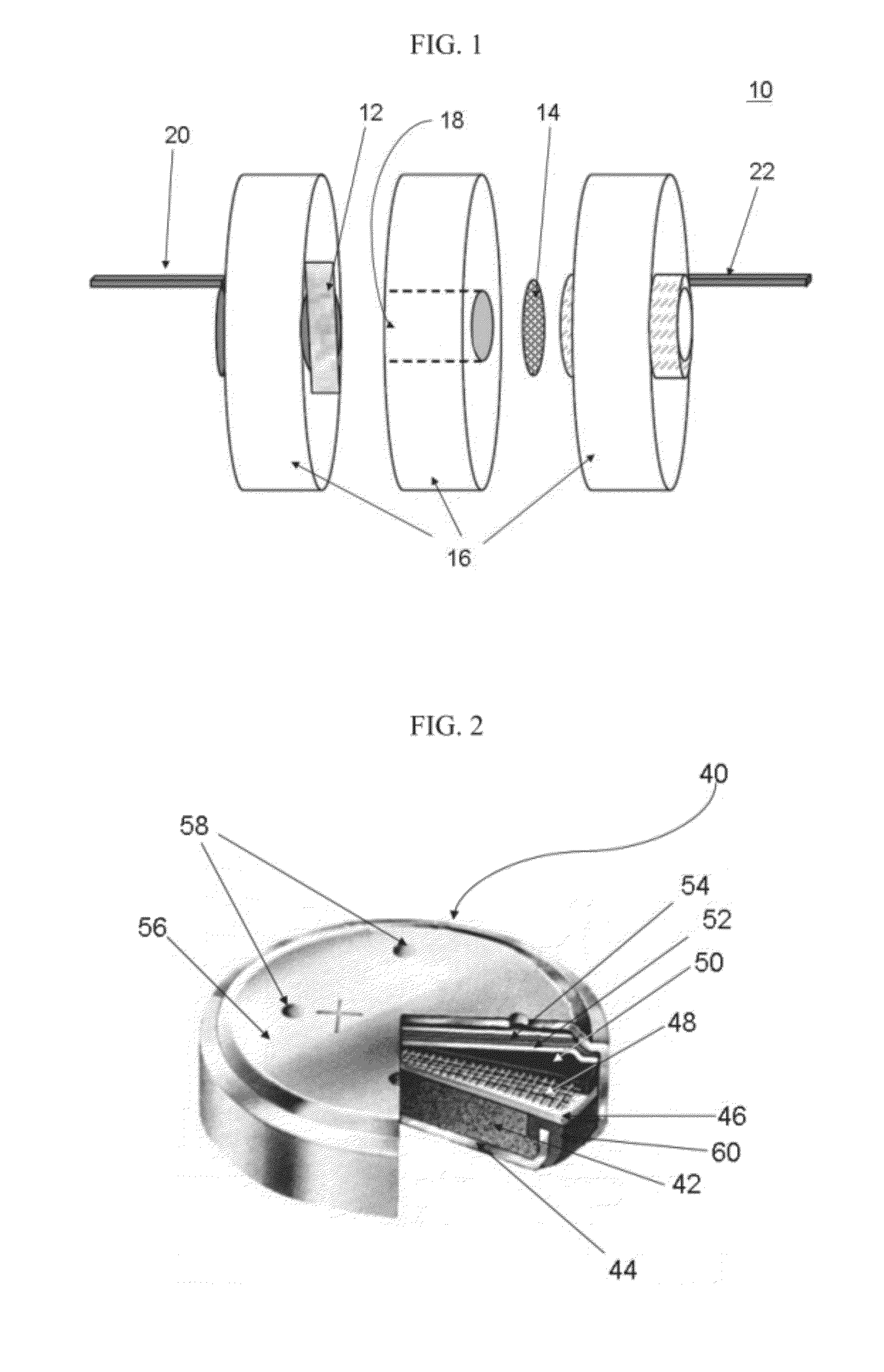
[0199]Silicon-air battery discharge performances under several current densities in ambient temperature were carried out in a cell configuration following the exemplary battery presented in FIG. 1. Data were collected using n++ As-doped silicon anode (see also the red curve, denoted with circle symbols in FIG. 3). Prior to any discharge, the cell was held at OCP for 4 hours, allowing the electrolyte to properly wet the porous carbon constitutes the air electrode. Discharge was terminated in a cut off voltage of 0.5 V.

[0200]FIG. 6 presents comparative discharge plots of an exemplary silicon-air batteries according to some embodiments of the present invention, using EMI.(HF)2.3F RTIL electrolyte at different constant current densities.

[0201]As can be seen in FIG. 6, the capacity values obtained for the silicon-air battery discharges are 3, 12.5, 15.25 and 26.7 mA per hour at current densities of 10, 50, 100 and 300 μA per cm2, respectively. As ...


PUM


Abstract

Silicon-oxygen batteries comprising a silicon anode as chemical fuel, an air-cathode for dissociating oxygen and a non-aqueous electrolyte, and applications using the same are provided. The silicon-batteries may utilize air for generating oxygen.

Description

FIELD AND BACKGROUND OF THE INVENTION[0001]The present invention, in some embodiments thereof, relates to energy conversion, and more particularly, but not exclusively, to electrochemical cell systems which utilize air and which can be utilized for forming batteries and fuel cells, and to applications of such batteries and fuel cells.[0002]The continuous search for clean, sustainable and cost-effective source of energy has pushed materials and electrochemical sciences to development of new materials and technologies for portable power sources. The prime objectives include reducing the size of the power source and at the same time increasing its energy or power density, along-side of reducing cost and toxic hazards while increasing safety and ease of use thereof.[0003]Electrochemical cell devices, referred to in the art as “batteries”, are composed of one or more electrochemical or voltaic cells, which store chemical energy and provide it as available electricity due to a potential d...

Claims


Application Information

Patent Timeline
IPC IPC(8): H01M8/22H02J7/00H05K7/00
CPCH01M4/38H01M2300/002H01M12/06
Inventor EIN-ELI, YAIRMACDONALD, DIGBY DONALD
Owner PENN STATE RES FOUND
Why Eureka
Try Eureka