Resonator structures and method of making

a resonator and structure technology, applied in the field of resonator structures, can solve the problems of brittle ceramic nature of dielectric materials and challenges the processing of required resonator structures

Active Publication Date: 2012-12-06
GENERAL ELECTRIC CO
View PDF8 Cites 5 Cited by
  • Summary
  • Abstract
  • Description
  • Claims
  • Application Information

AI Technical Summary

Benefits of technology

[0003]Briefly, in one embodiment, a resonator is provided. The resonator includes a plurality of layers, including a ceramic layer and a metallic layer. The ceramic and metallic layers are configured in a Swiss-roll form such that the neighboring ceramic layers are separated by the metallic layer. Further, the ceramic layer includes materials that have a dielectric constant of at least about 10 and dielectric loss tangent less than about 0.01 in the frequency range of about 1 KHz to about 100 MHz.
[0004]In one embodiment, a method of forming a resonator is disclosed. The method includes the steps of disposing a metallic layer, depositing a dielectric ceramic layer, and forming a Swiss-roll structure of the metallic and ceramic layers. Further steps include heat treating the resultant Swiss-roll structure in vacuum, inert atmosphere, or reducing atmo...

Problems solved by technology

The conflicting properties of metal and ceramic pose a challenge in realizing dielectric materials having high permittivity and low loss processed in a way to form a thin layered monolithic structure between th...

Method used


Image

  • Resonator structures and method of making
  • Resonator structures and method of making
  • Resonator structures and method of making

Examples


examples

[0040]The following examples illustrate methods and embodiments in accordance with the invention, and as such, should not be construed as imposing limitations upon the claims.

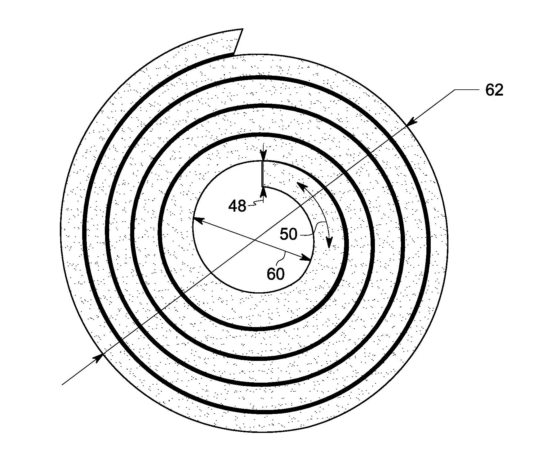
[0041]In one example, a sintered Swiss-roll structure 94 is prepared using the steps mentioned herein. A copper strip was prepared by cold working. The stresses of the cold worked metal strip were removed by heat treating the metal strip in an argon atmosphere at a temperature about 750° C., and cooling it at a slow rate. In an alternate example, the metallic strip was formed using hot working. The metallic strip formed by cold working or hot working was flattened using a hammer. The metallic surface was further rubbed using an emery paper of grit size 60 to prepare a rough surface configured to have sufficient interactions with the subsequent overlaying ceramic layer. Techniques such as sand blasting could be used alternatively for the surface preparation of metallic strip.

[0042]The surface-prepared metal stri...


PUM

PropertyMeasurementUnit
Lengthaaaaaaaaaa
Thicknessaaaaaaaaaa
Thicknessaaaaaaaaaa

Abstract

A resonator in the Swiss-roll structure, method of making the resonator structure and the system employing the resonator are disclosed. The resonator includes a plurality of layers, including a ceramic layer and a metallic layer. The ceramic and metallic layers are configured in a Swiss-roll form such that the neighboring ceramic layers are separated by the metallic layer. Further, the ceramic layer includes materials that have a dielectric constant of at least about 10 and dielectric loss tangent less than about 0.01 in the frequency range of about 1 KHz to about 100 MHz. The method of forming the resonator includes the steps of disposing a metallic layer, depositing a dielectric ceramic layer, and forming a Swiss-roll structure of the metallic and ceramic layers. Alternate method includes swaging the dielectric material filled metal tubes and forming into Swiss-rolls. Further steps include heat treating the resultant Swiss-roll structure in vacuum, inert atmosphere, or reducing atmosphere to form a monolithic Swiss-roll structure, such that the air gap between turns of the Swiss-roll structure is less than about 1 μm.

Description

BACKGROUND[0001]The invention relates generally to resonator structures. More particularly, the invention relates to resonators and method of making the resonator structures.[0002]Self-resonating electromagnetic resonating structures are used in many different applications like microwave filters, RF antennas etc. The frequency of resonance of an electromagnetic resonating structure is inversely related to the diameter of the structure. However, for high power applications, it is required to have resonance frequencies lower than 1 MHz while keeping the diameter of structure still less than about 20-50 cm. These requirements can be met by embedding the resonating structure in high dielectric permittivity material to enhance the self-capacitance and thereby reduce the frequency of resonance. The conflicting properties of metal and ceramic pose a challenge in realizing dielectric materials having high permittivity and low loss processed in a way to form a thin layered monolithic structu...

Claims


Application Information

Patent Timeline
IPC IPC(8): H02J17/00H01F41/22H01P7/00
CPCH01P7/00Y10T29/4902H01P11/008H02J17/00Y10T29/49117H02J50/12
Inventor KRISHNA, KALAGA MURALIREDDY, SUDHAKAR EDDULAMATANI, LOHIT
Owner GENERAL ELECTRIC CO
Why Eureka
Try Eureka