System for furnace slopping prediction and lance optimization

a technology of system and lance, applied in the direction of furnaces, manufacturing converters, lighting and heating apparatus, etc., can solve the problems of ejection of molten steel and slag therefrom, cost and time consumption, yield loss and cost, etc., and achieve the effect of reducing the requirement for re-blow

Active Publication Date: 2012-12-13
TENOVA GOODFELLOW INC
View PDF0 Cites 3 Cited by
  • Summary
  • Abstract
  • Description
  • Claims
  • Application Information

AI Technical Summary

Benefits of technology

[0018]Yet another object of the invention is to monitor the vibration of the lance corresponding to oxygen jet impingement onto the surface of the bath and correlate tha

Problems solved by technology

Many factors that cannot be accurately measured have influence on the process and therefore the process model is usually inadequate to cause a desired outcome every time.
This is costly and time consuming.
In addition, the process may cause slopping of the charge and ejection of steel, which results in yield loss and is costly.
When the slopping becomes extreme, the charge can surge over the upper rim of the vessel, resulting in an ejection of molten steel and slag therefrom.
While this may be effective, it may slow the process and limit production rates.
Also, the time at which the actions of reducing the blowing rate and the lance height need to be implemented are variable and not well known.
The excess iron oxide can influence slag chemistry and may increase the amount of slopping.
The reagent calcium carbide is expensive and the effective amount can be variable.
In addition, the optimal time of addition may not be known, so the reagent may be consumed prior to the actual time that it is needed.
In practice, the microwave device is difficult to main

Method used


Image

  • System for furnace slopping prediction and lance optimization
  • System for furnace slopping prediction and lance optimization
  • System for furnace slopping prediction and lance optimization

Examples


example 2

Incipient Slopping Prediction

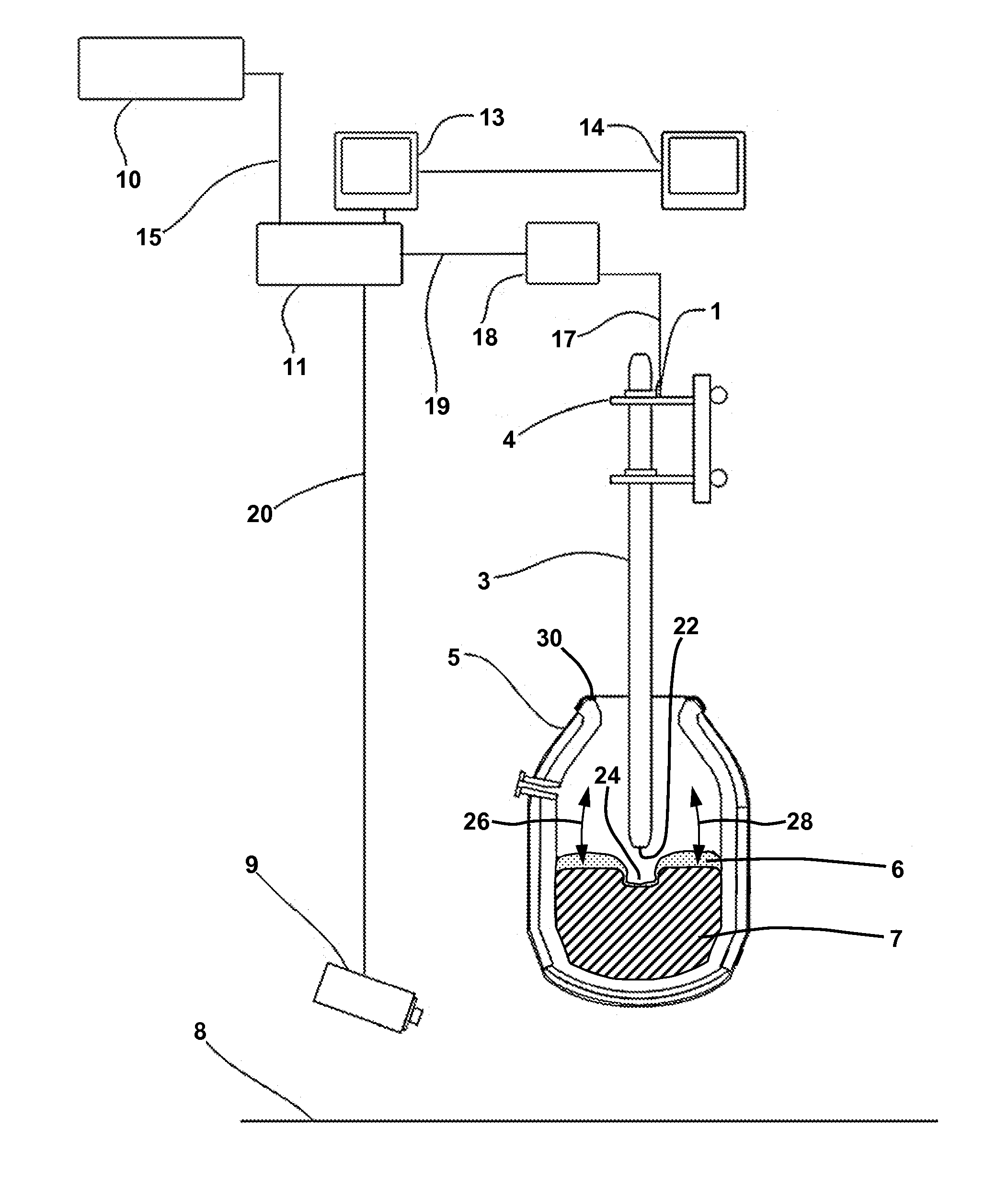
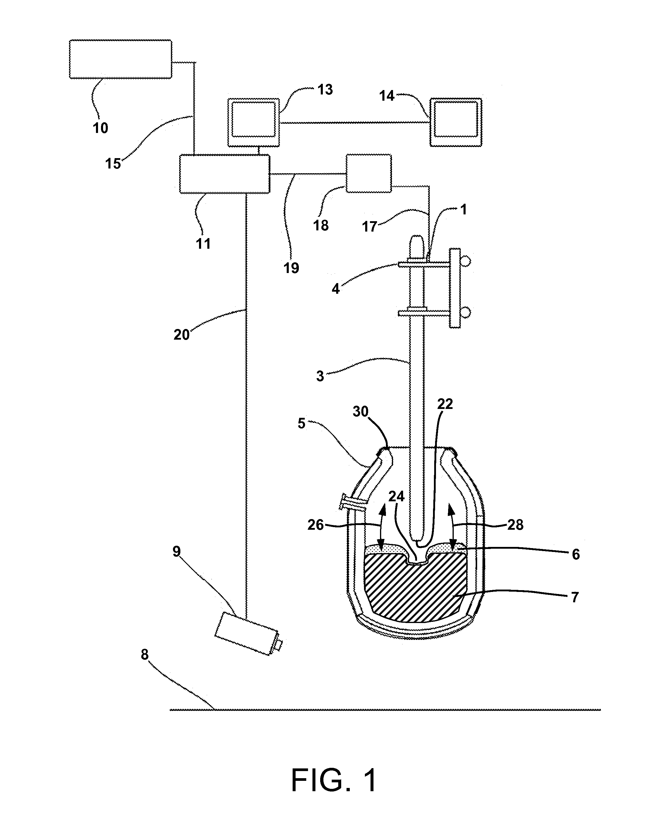
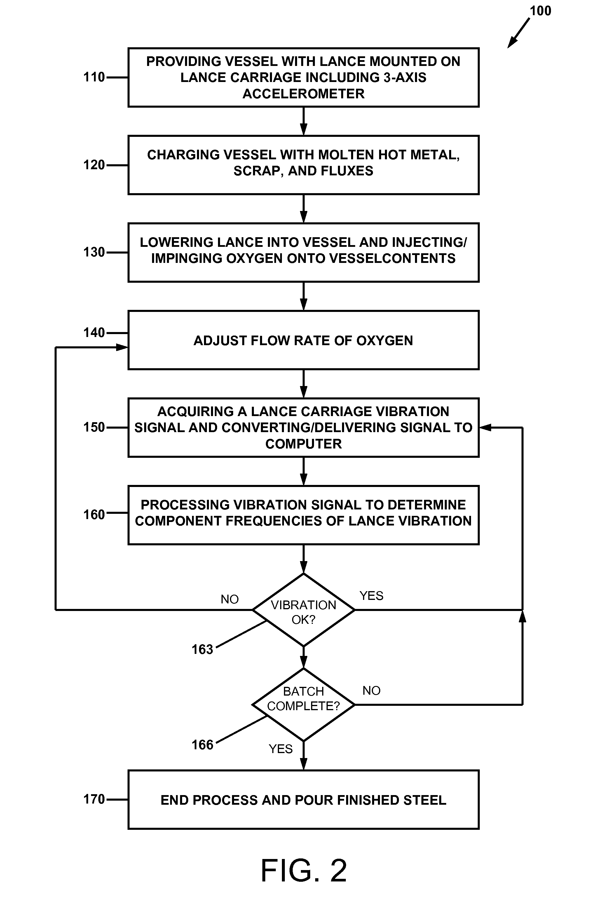
[0054]A BOF vessel 5 was charged with molten hot metal, scrap and fluxes. After charging the furnace 5, the furnace 5 was rotated to the vertical position and a lance 3 was lowered into the vessel 5. Oxygen was injected through the lance 3 and its force of impingement as it exited the lance ports formed a cavity 24 on the surface of the charge 6 / 7. As oxygen was injected during the process, the removal of carbon and the formation of a liquid slag 6 proceeded.

[0055]A three-axis integrated circuit piezoelectric accelerometer 1 was mounted on the lance carriage 4 to monitor the lance carriage vibration resulting from oxygen flow through the lance 3 and from other process variables. The vibrations were converted to an analog electrical signal that was digitized using a data acquisition system 18 and computer 11.

[0056]The digital signal was processed using a Fourier Transform to determine the component frequencies. Vibration amplitude in the frequency range o...

example 3

Slopping Detection

[0058]A BOF vessel 5 was charged with molten hot metal, scrap and fluxes. After charging the furnace 5, the furnace 5 was rotated to the vertical position and a lance 3 was lowered into the vessel 5. Oxygen was injected through the lance 3 and its force of impingement as it exited the lance ports formed a cavity 24 on the surface of the charge 6 / 7. As oxygen was injected during the process, the removal of carbon and the formation of a liquid slag 6 proceeded.

[0059]A three-axis integrated circuit piezoelectric accelerometer 1 was mounted on the lance carriage 4 to monitor the lance carriage vibration resulting from oxygen flow through the lance 3 and from other process variables. The vibrations were converted to an analog electrical signal that was digitized using a data acquisition system 18 and computer 11.

[0060]The digital signal was processed using a Fourier Transform to determine the component frequencies. Vibration amplitude in the frequency range of 4-500 Hz ...

example 4

End Point Determination

[0062]A BOF vessel 5 was charged with molten hot metal, scrap and fluxes. After charging the furnace 5, the furnace 5 was rotated to the vertical position and a lance 3 was lowered into the vessel 5. Oxygen was injected through the lance 3 and its force of impingement as it exited the lance ports formed a cavity 24 on the surface of the charge 6 / 7. As oxygen was injected during the process, the removal of carbon and the formation of a liquid slag 6 proceeded.

[0063]A three-axis integrated circuit piezoelectric accelerometer 1 was mounted on the lance carriage 4 to monitor the lance carriage vibration resulting from oxygen flow through the lance and from other process variables. The vibrations were converted to an analog electrical signal that was digitized using a data acquisition system 18 and computer 11.

[0064]The digital signal was processed using a Fourier Transform to determine the component frequencies. Vibration amplitude in the frequency range of 3600-4...


PUM

PropertyMeasurementUnit
Flow rateaaaaaaaaaa
Heightaaaaaaaaaa
Frequencyaaaaaaaaaa

Abstract

A method of making steel in a vessel comprising providing a lance for blowing oxygen on the surface of the steel in the vessel, the lance joined to a lance carriage and in communication with an accelerometer, the accelerometer in signal communication with a data acquisition module and a computer; charging the vessel with materials for steel making; lowering the lance into the vessel and injecting oxygen into the materials; acquiring a signal from the accelerometer indicative of lance vibration; processing the vibration signal to determine component frequencies of lance vibration; comparing the levels of the component frequencies to desired operating values; and adjusting at least one steel making process parameter based on the level of at least one of the component frequencies. The steel making process parameter to be adjusted may be oxygen flow rate through the lance.

Description

TECHNICAL FIELD[0001]Control of a basic oxygen furnace in steel making, and more particularly, optimization of lance oxygen flow rate, slopping prediction and / or detection, and end point determination of a batch of steel.BACKGROUND ART[0002]In the top blown basic oxygen steel making process, a vessel is charged with a liquid carbon saturated iron alloy referred to as hot metal, scrap steel, and fluxes that provide CaO and MgO to the process. A water-cooled lance is inserted into the vessel through which oxygen is injected at supersonic speeds. The lance has at least one port and often multiple ports at the tip through which the oxygen exits and impinges onto the surface of the charge. The oxygen reacts with the metallic and carbon components of the charge, and heat is generated by the exothermic reactions. Over time, the oxygen reacts chemically and oxidizes substantially all of the silicon and aluminum that were present in metallic form in the charge.[0003]In addition, most of the ...

Claims


Application Information

Patent Timeline
IPC IPC(8): C21C5/30
CPCB22D2/00C21C5/462C21C5/4673F27D2021/0085F27D21/0028F27D2019/0068F27D19/00C21C5/28C21C5/30
Inventor KEMENY, FRANK L.WALKER, DAVID I.
Owner TENOVA GOODFELLOW INC
Why Eureka
Try Eureka