Electrolyte Enhanced Microbial Fuel Cell

a fuel cell and microorganism technology, applied in the field of microorganism enhanced microbial fuel cells, can solve the problems of reducing power generation, reducing voltage efficiency, and acidification of the anode compartment and a ph gradient between the compartments, so as to facilitate efficient energy production, facilitate fluid use, and reduce the effect of conductivity

Inactive Publication Date: 2012-12-20
DOW GLOBAL TECH LLC
View PDF4 Cites 17 Cited by
  • Summary
  • Abstract
  • Description
  • Claims
  • Application Information

AI Technical Summary

Benefits of technology

[0009]It should be appreciated that the above referenced aspects and examples are non-limiting, as others exist within the present invention, as shown and described herein. The processes for utilizing the microbial fuel cells of the invention facilitate the use of fluids having a low conductivity in such fuel cells without the need for a buffer. The fuel cells and processes of the invention facilitate efficient production of energy from fluids containing biodegradable materials and efficient removal of biodegradable materials from fluids in an environmentally friendly manner. The microbial fuel cells of the invention may be operated in a fashion such that appreciable acidification of the fluid is avoided. The microbial fuel cells of the invention do not require the use of undesirable chemicals as oxidants. The microbial fuel cells can be operated at low noble metal loading levels and demonstrate high current densities such as about 10 A / m2 or greater, and more preferably about 15 A / m2 or greater. The microbial fuel cells of the invention with feed streams having a low or no buffering capacity demonstrate high current densities such as about 3 A / m2 or greater, more preferably 7 A / m2 or greater and most preferably about 15 A / m2 or greater. The microbial fuel cells of the invention with feed streams having low conductivity demonstrate high current densities such as about 3 A / m2 or greater, more preferably 7 A / m2 or greater and most preferably about 15 A / m2 or greater. The microbial fuel cells of the invention and processes of the invention reduce ohmic, ionic and mass transfer resistance. The process of the invention provides three potential environmental benefits, generation of electricity from waste streams, reduction of the amount of biodegradable materials in waste streams and conversion of environmentally unacceptable salt containing streams to streams which meets discharge standards.

Problems solved by technology

Failure to move the hydrogen ions from the anode compartment or hydroxide ions to the anode compartment can result in acidification of the anode compartment and a pH gradient between the compartments.
The practical effect of the pH gradient is a drop in voltage efficiency, which consequently decreases power generation.
Microbial fuel cells provide the promise of environmentally friendly power generation and fluid purification and also present several technical challenges in addition to the pH gradient problem noted above.
Most waste water streams have limited conductivity which inhibits the transmission of ions between the cathode and the anode.
The addition of buffers to assist in the purification of waste water is counterproductive.
Noble metals are very expensive and impact the cost effectiveness of microbial fuel cells.
Microbial fuel cells having such an oxidation agent are not environmentally friendly nor are they economically sustainable.
Activation losses are caused by the slowness of the reactions taking place on the surface of the electrode.
Ohmic losses result from the voltage drop due to the straightforward resistance to the flow of electrons through the materials of the electrodes and the various interconnections and electron conduits as well as the resistance to the flow of ions through the electrolyte and the ion conduit.
Mass transport or concentration losses result from the change in the concentration of the reactants at the surface of the electrodes as the fuel is used.
It is not environmentally friendly to discharge such streams directly into the environment.

Method used


Image

  • Electrolyte Enhanced Microbial Fuel Cell
  • Electrolyte Enhanced Microbial Fuel Cell
  • Electrolyte Enhanced Microbial Fuel Cell

Examples


specific embodiments of invention

[0054]The following examples are included for illustrative purposes only and are not intended to limit the scope of the invention. Unless otherwise stated, all parts and percentages are by weight.

Assembly of Microbial Fuel Cell

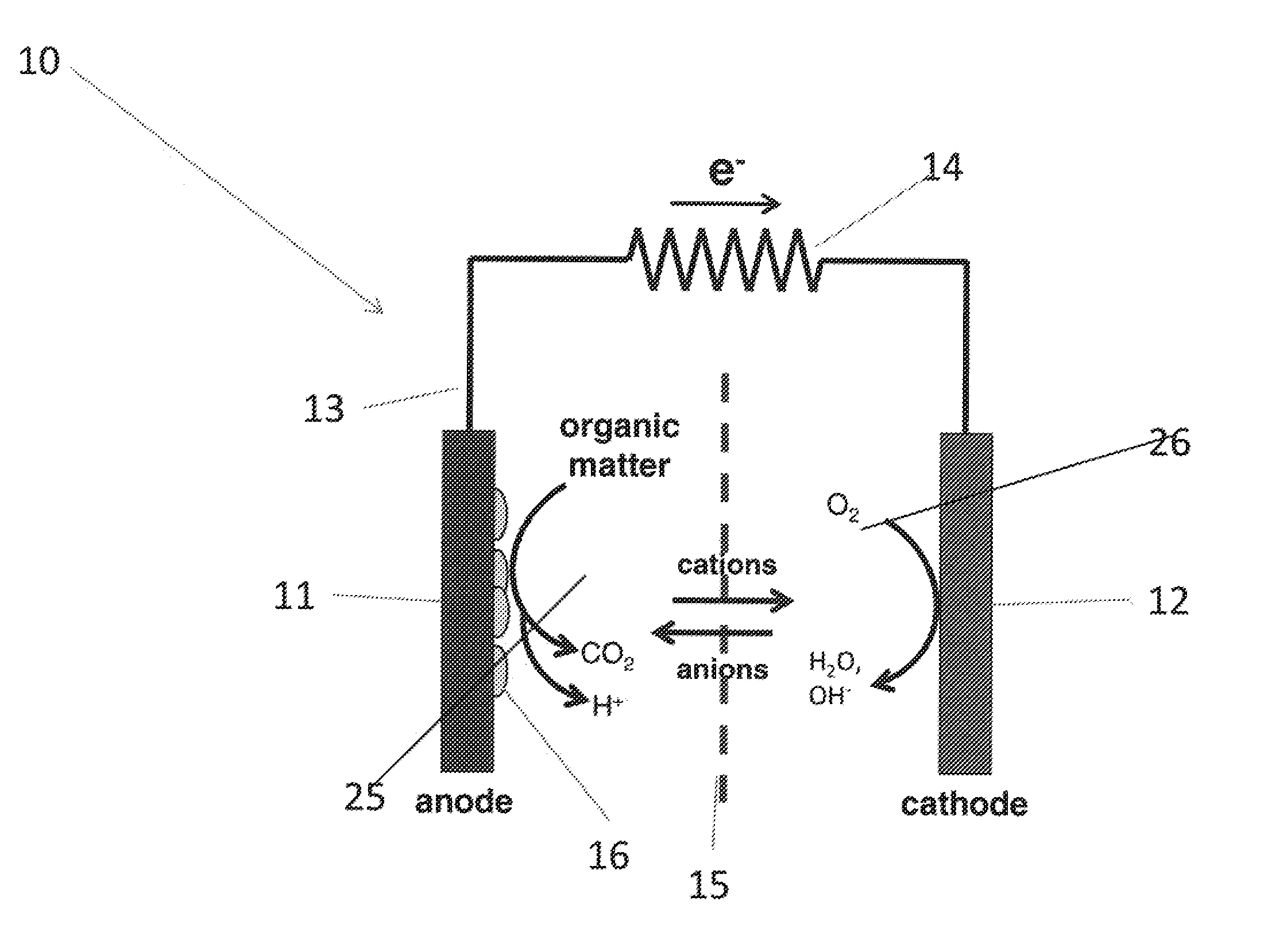
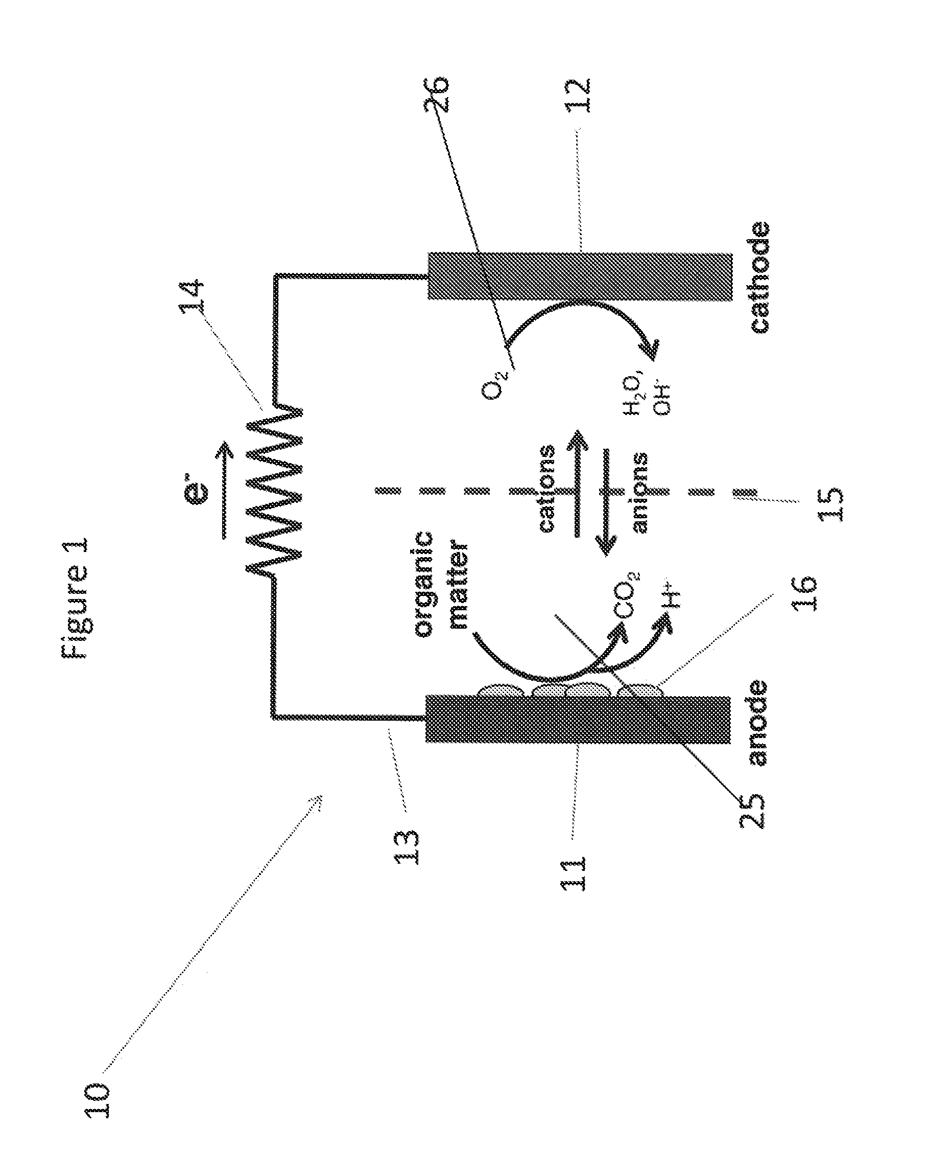
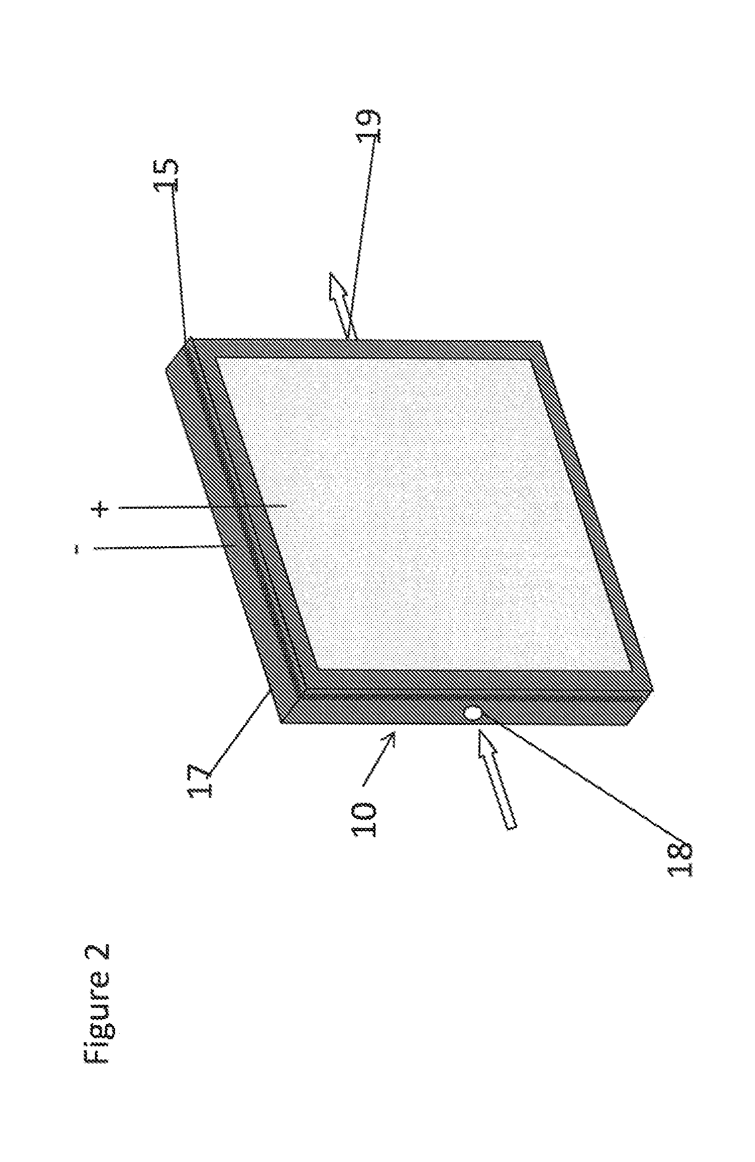
[0055]A chamber 1.5 cm wide, about 4 cm long and 0.45 cm deep is machined in a 3 cm×6 cm×0.9 cm piece Lucite. Ports are drilled into the piece to serve as inlet and outlet ports for solution flow. Two small holes are drilled in the bottom of the chamber for wire leads. One longer wire, Au, is used as the electron conduit and another shorter wire, Pt, is used as an unloaded voltage probe. The lead wires are sealed into place using epoxy. A piece of carbon felt 1.52 cm×3.0 cm×0.45 cm is placed in the chamber. An anion exchange membrane, a film prepared from a polyolefin binder and ground ion exchange resin, is placed over the felt, then a cathode consisting of Pt / C on carbon paper support is cut to 1.5 cm×3 cm and placed on the membrane opposite the carbon felt ...


PUM

PropertyMeasurementUnit
conductivityaaaaaaaaaa
current densitiesaaaaaaaaaa

Abstract

The present invention relates to a process comprising A) providing a microbial fuel cell comprising i) an anode containing one or more electrically conductive materials which is arranged to provide flow paths for electrons through the electrically conductive material, ii) microbes in electrical contact with the anode iii) a cathode containing one or more electrically conductive materials iv) a catholyte, v) a conduit for electrons in contact with both the anode and the cathode which is a part of a circuit; B) introducing a mixture of one or more electrolytes or one or more electrolytes dissolved in a first fluid with a second fluid containing biodegradable material; C) contacting the mixture of B) with the anode in the presence of microbes; D) contacting the cathode with a catholyte; E) removing from the microbial fuel cell the fluid mixture.

Description

CROSS REFERENCE TO RELATED APPLICATIONS[0001]This application claims priority from U.S. Provisional Application Ser. No. 61 / 315,541 filed Mar. 19, 2010 titled ELECTROLYTE ENHANCED EFFICIENCY MICROBIAL FUEL CELL, incorporated herein by reference.FIELD OF THE INVENTION[0002]The present invention relates to microbial fuel cells. The present invention further relates to processes for improving the operation of fuel cells utilizing electrolytes. The present invention further relates to processes for producing electricity from fluids containing biodegradable materials, such as waste water. In addition, the present invention relates to processes for removing biodegradable materials from fluids containing biodegradable materials, such as waste water. In addition, the present invention relates to a process for reducing the electrolyte level of effluents from industrial processes and waste treatment.BACKGROUND[0003]Microbial fuel cells are well known. Patents disclosing and claiming processes...

Claims


Application Information

Patent Timeline
Patent Type & Authority Applications(United States)
IPC IPC(8): H01M8/16
CPCY02E60/527H01M8/16Y02E60/50
Inventor WALLIN, STEN A.MATTEUCCI, SCOTT T.
Owner DOW GLOBAL TECH LLC
Why Eureka
Try Eureka