
Rapid converting of sheet material methods and apparatus

a sheet material and conversion method technology, applied in the field of sheet material conversion, can solve the problems of less material used in the press, the method of making parts such as gaskets and prototypes with computerized numerical control (hereinafter “cnc”) can be time-consuming and more expensive than desirable, so as to reduce material distortion, reduce cost, and reduce the effect of material distortion

Inactive Publication Date: 2012-12-27
RAPID CONVERTING
View PDF6 Cites 32 Cited by
  • Summary
  • Abstract
  • Description
  • Claims
  • Application Information

AI Technical Summary

Benefits of technology

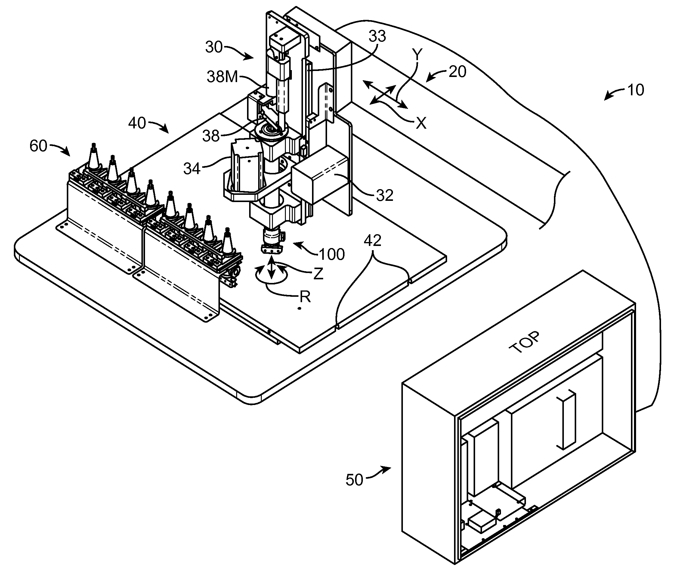
[0010]The methods and apparatus of the embodiments described herein can provide a means for a user such as a customer located remote from a cutting machine to cut a part. The user can instruct the cutting machine apparatus to cut the part to the user's specification in many ways, for example such that the user can instruct the cutting machine apparatus without having knowledge of the machine's cutting processes or construction. The methods and apparatus of the embodiments described herein can convert cutting machine processes into an image of the part to be cut such that the user can easily understand and view the image of the part to be cut remote from the cutting machine apparatus. The means for a customer user to cut a part may comprise components of a processor system, such as a processor, a computer readable medium and a display remote from the cutting machine apparatus. The image of the part to be cut can be shown on the display of the customer user. The customer user can be at a first location such as at home or at an office and the cutting machine can be located at a second location remote from the user, for example in another building or in another town when the image is viewed. The user processor coupled to the user display may comprise instructions of a computer program stored on a computer readable medium such as a computer memory, and the computer program may comprise instructions to display the image of the part to be cut to the user. The image displayed to the customer user may comprise an image transmitted from a location remote from the customer user.
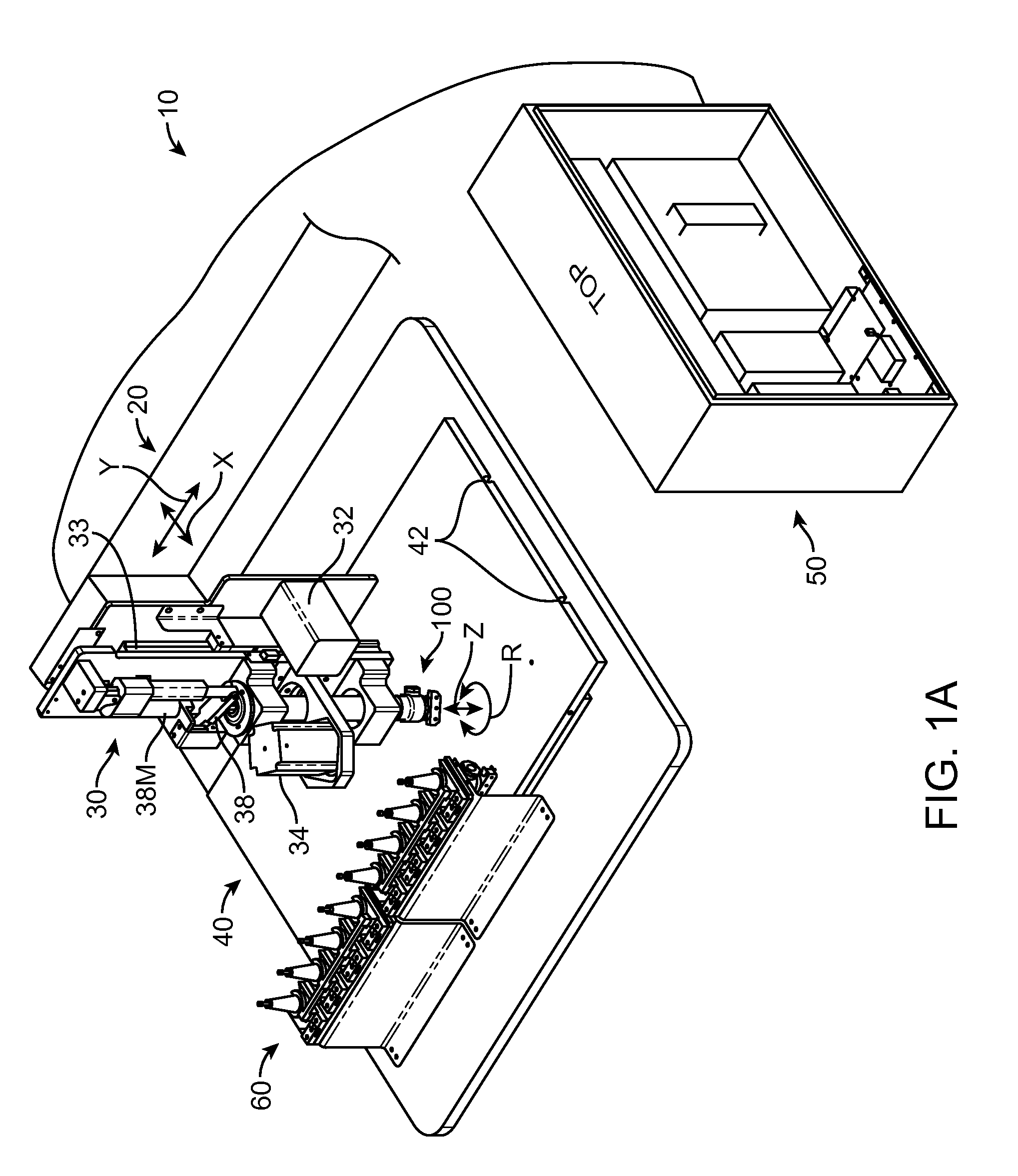
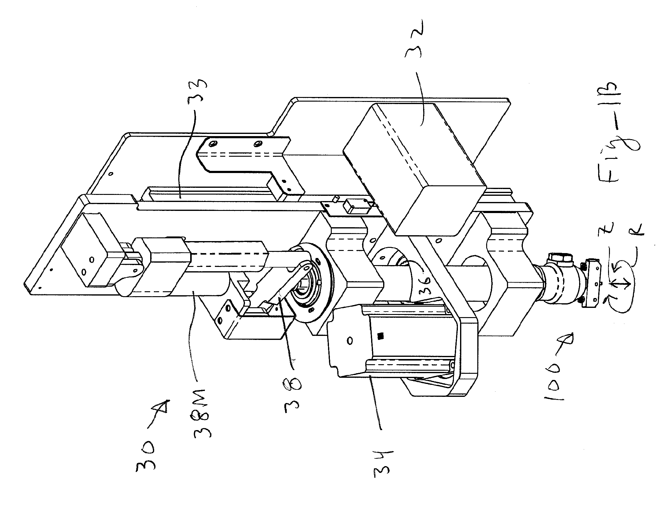
[0011]In many embodiments, the apparatus comprises a head and cutting tool coupled to a computer system to cut a part having a profile from a sheet of material positioned on a support. The cutting tool may comprise a blade to cut the material when positioned on the head, and an angle of the blade can be adjusted under computer control so as to cut the sheet material in accordance with the profile of the part. The blade may comprise an elongate blade such that the part can be cut rapidly, and the blade aligned in accordance with the cut profile of the part. The cutting tool may comprise a first component to cut the sheet material with force to the blade and a second component to maintain the angle of the cutting angle of the blade, such that the cutting angle can be controlled accurately. The cutting tool may comprise a first curved surface coupled to a second curved surface so as to adjust an angle of the blade relative to the upper surface of the sheet and such that the sheet is cut uniformly. A processor system can be coupled to the cutting tool, and the processor system may comprise a factory processor server remote from the user. The user located remote from the cutting tool can upload a drawing and input selections to the server. The server can download a file comprising cut profiles and material information in response to the uploaded file and conditions of the factory floor such as the tooling available. For example, the user can view an initial image comprising a first initial profile of the part of the drawing overlaid on a second cut profile corresponding to the cut part, such that the user can confirm the part cut with the cutting tools and process is suitable. A bed can be coupled to the cutting machine to secure the sheet material such that the sheet material does not shift positions during the cutting of the sheet material. This bed can include a vacuum system to hold down the material and may comprise of sintered material so as to distribute the vacuum around an outer portion of the material, and the outer portion may encompass a perimeter of the material. A press plate can be used to hold the sheet material on the bed in a substantially unstrained manner, so as to decrease distortion of the material when cut, for example so as to decrease distortion of cut elastomer material, and the press plate can be used with a sheet material set-up process to position and hold the material on the bed so as to decrease distortion of the cut part.

Problems solved by technology

The prior methods of making parts such as gaskets and prototypes with computerized numerical control (hereinafter “CNC”) can be more expensive and time consuming than would be desirable in at least some instances.
In at least some instances making a metal press that corresponds to a gasket can be time consuming and more expensive than would be ideal.
Also, at least some of the known methods of manufacturing metal presses can waste at least some of the material used to make the press and require more energy than would be ideal in at least some instances.
At least some prior manufacturing processes use a cutting tool, with a blade shaped to cut the entire gasket with one punching cycle, and strike the shaped cutting tool against a cutting table, and in at least some instances there can be clearance above the cutting table such that the cutting of the part is incomplete, sometimes referred to as a kiss-cut, or there can be interference of the shaped blade cutting into the cutting table which can result in wear of the cutting blade, the table and associated machinery in at least some instances.
Although lasers can be used to cut material, the prior methods of cutting with lasers can be less than ideal in at least some instances.
At least some of the current methods of cutting lasers may cause a zone of thermal damage in at least some instances when the material is cut.
Also, in at least some instances lasers can produce toxic gases and vapor material in at least some instances, and such laser systems may use a debris removal system that can be more complex than would be ideal.
Although water jets can be used to cut material, in at least some instances water jets may use an abrasive material that can contaminate the cut material in at least some instances.
For example, foam can be contaminated with an abrasive of the water jet in at least some instances, and wetting of the material can make handling more difficult and result in contamination in at least some instances.
Although three dimensional rapid prototyping, for example with overlapping laser beams, can be used to manufacture at least some prototype parts with stereo-lithography, such systems can be more expensive and complex than would be ideal.
Also, the use of photo-reactive materials can limit to at least some extent the materials that can be formed with the stereo-lithography systems, and at least some of the prior resins can be toxic in at least some instances.
For example, lateral stresses of the material may result in distortion of the pattern when cut in at least some instances.

Method used


Image

  • Rapid converting of sheet material methods and apparatus
  • Rapid converting of sheet material methods and apparatus
  • Rapid converting of sheet material methods and apparatus

Examples


Embodiment Construction

[0031]Embodiments of the present invention can be used in many ways to improve the manufacturing of sheet materials and to provide manufactured materials in an efficient manner with a processor system The ordering and manufacturing processes allows a user to order a part remotely from the cutting tool apparatus and view an image of the part to be received with the image of the part sent. The order and manufacture process can be implemented with a processor system that may comprise a user computer processor, a factory server processor, and a apparatus and processor to cut the material. The user and the user processor can be located remotely from the cutting tool apparatus, and instructions of the processor system can be codified in software running on the processors. The cutting tool coupled to the processor system can convert sheet material to finished goods with instructions of the processor system based on input of the remote user. For example, elastomer sheet goods can be manufac...


PUM

PropertyMeasurementUnit
thickaaaaaaaaaa
distanceaaaaaaaaaa
angleaaaaaaaaaa

Abstract

Methods and apparatus provide an input for a user located remote from a cutting machine to cut a part. The user can instruct the cutting machine to cut the part to the user's specification in many ways, for example such that the user can instruct the cutting machine without having knowledge of the machine's cutting processes or construction. The methods and apparatus of the embodiments described herein can convert a machine processes into an image of the part to be cut such that the user can easily view and understand the image of the part to be cut remote from the cutting machine.

Description

CROSS-REFERENCES TO RELATED APPLICATIONS[0001]The present Continuation application claims priority to PCT Application No. PCT / US2010 / 056083, filed 9 Nov. 2010, entitled “Rapid Converting of Sheet Material Methods and Apparatus”, which application claims priority to U.S. Provisional Patent Application Ser. No. 61 / 259,463, filed 9 Nov. 2009, entitled “Rapid Converting of Sheet Material Methods and Apparatus”, the full disclosures of which are incorporated herein by reference.BACKGROUND OF THE INVENTION[0002]The present invention is related to the conversion of sheet material to finished goods such as machined parts, gaskets, shims and sheet metal. Although specific reference is made to the converting of sheet material to gaskets, embodiments as described herein will have application to many industries where sheet material is converted to a part, for example rapid prototyping.[0003]The prior methods of making parts such as gaskets and prototypes with computerized numerical control (her...

Claims


Application Information

Patent Timeline
Patent Type & Authority Applications(United States)
IPC IPC(8): B26D7/26G06F19/00
CPCB26D5/00B26D5/005B26D7/018B26F1/3826B26D11/00B26F1/3813B26D7/2628Y10T83/8776Y10T83/8867
Inventor EDWARDS, GLENNBECHTEL, LORNEBECHTEL, MARIE
Owner RAPID CONVERTING
Learn More