Compact high efficiency remote LED module

a technology of led modules and led modules, applied in the field of solid-state lamps and modules, can solve the problems of high inefficiency of lamps, chronic and acute poisoning, and loss of as much as 95% of input energy, and achieve the effects of promoting heat conduction, improving thermal management features, and reducing heat sinks

Inactive Publication Date: 2013-01-03
CREE INC
View PDF21 Cites 67 Cited by
  • Summary
  • Abstract
  • Description
  • Claims
  • Application Information

AI Technical Summary

Benefits of technology

[0016]The present invention provides LED based light sources or modules with improved thermal management features that allow it to operate at a lower temperature, which in turn can allow the LEDs in the modules to be driven by a higher drive signal, or for the bulbs to have a smaller heat sink. The LED modules generally comprise an optical element on a heat sink, with a remote phosphor over the optical element so that light from the optical element's LEDs passes through the remote phosphor, and a remote power supply that provides electrical power to the LEDs. The present invention also comprises features, such as a conductive adapter, that promote the conduction of heat from the LEDs to the features of a light fixture in which the LED module is mounted. In some embodiments an adapter can be used to mount the LED module's heat sink to the light fixture, with the adapter being thermally conductive to transfer heat from the heat sink to the fixture. Utilizing thermally conductive elements and surface features of the light fixture to conduct heat away from the LED module and dissipate heat into the ambient allows the LEDs to operate at a lower temperature, higher efficiency and with better reliability.
[0017]The remote phosphor can comprise a thermally conductive material that aids in the transfer of heat generated during the conversion process to the ambient or the heat sink. The LEDs and remote phosphor can also be arranged so that the LED module generates light with an omnidirectional emission pattern. The emission can have a good color temperature, color rendering index, and color consistency at different viewing angles, making the bulbs suitable for general illumination. The LED modules and light fixtures according to the present invention are also arranged so that the LED module power supply unit can be spatially remote and thermally essentially insulated from the light generating elements of the LED module. This reduces or eliminates heat generation in the vicinity of the power supply unit, thereby allowing it to operate at a lower temperature, higher reliability, and with greater efficiency.

Problems solved by technology

However, such lamps are highly inefficient light sources, with as much as 95% of the input energy lost, primarily in the form of heat or infrared energy.
One common alternative to incandescent lamps, so-called compact fluorescent lamps (CFLs), are more effective at converting electricity into light but require the use of toxic materials which, along with its various compounds, can cause both chronic and acute poisoning and can lead to environmental pollution.
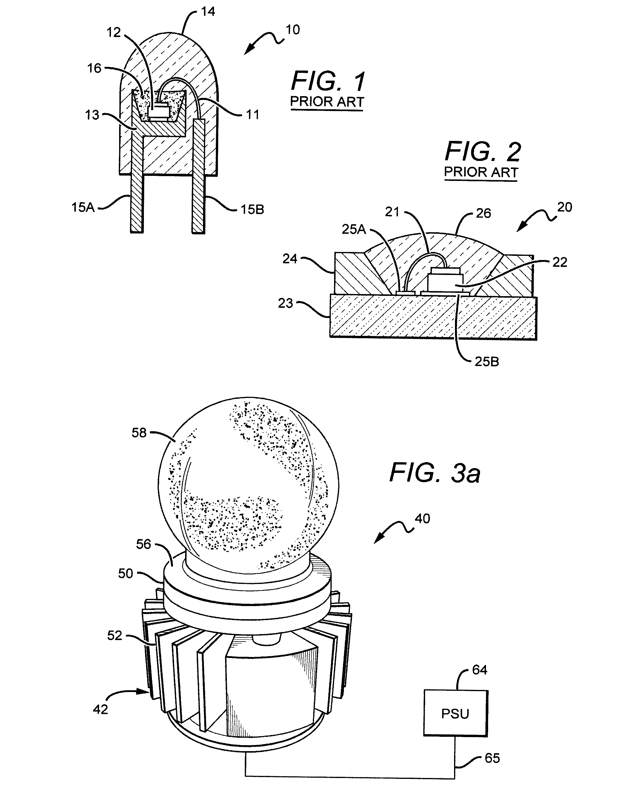
While the reflective cup 13 may direct light in an upward direction, optical losses may occur when the light is reflected (i.e. some light may be absorbed by the reflective cup due to the less than 100% reflectivity of practical reflector surfaces).
In addition, heat retention may be an issue for a package such as the package 10 shown in FIG. 1a, since it may be difficult to extract heat through the leads 15A, 15B.
LED chips which have a conversion material in close proximity or as a direct coating have been used in a variety of different packages, but experience some limitations based on the structure of the devices.
Further, in such cases the phosphor can be subjected to very high concentrations or flux of incident light from the LED.
Since the conversion process is in general not 100% efficient, excess heat is produced in the phosphor layer in proportion to the incident light flux.
In compact phosphor layers close to the LED chip, this can lead to substantial temperature increases in the phosphor layer as large quantities of heat are generated in small areas.
This temperature increase can be exacerbated when phosphor particles are embedded in low thermal conductivity material such as silicone which does not provide an effective dissipation path for the heat generated within the phosphor particles.
Such elevated operating temperatures can cause degradation of the phosphor and surrounding materials over time, as well as a reduction in phosphor conversion efficiency and a shift in conversion color.
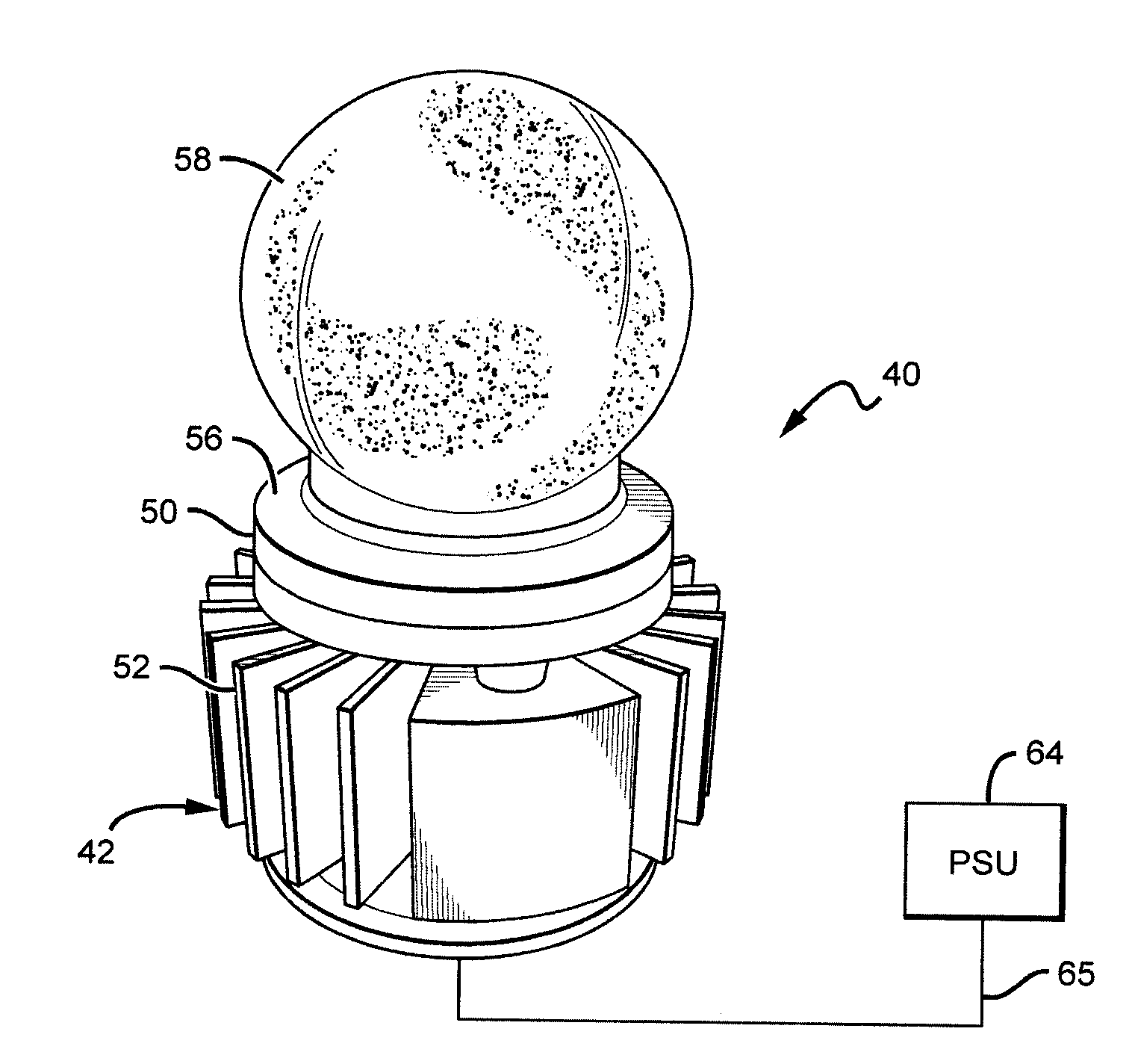
By comparison, one potential disadvantage of lamps incorporating remote phosphors arrangements is that the phosphor can be subject to inadequate thermally conductive heat dissipation paths.
Without an effective heat dissipation pathway, thermally isolated remote phosphors may suffer from elevated operating temperatures that in some instances can be even higher than the temperature in comparable conformal coated layers.
Stated differently, remote phosphor placement relative to the LED chip can reduce or eliminate direct heating of the phosphor layer due to heat generated within the LED chip during operation, but the resulting phosphor temperature decrease may be offset in part or entirely due to heat generated in the phosphor layer itself during the light conversion process and lack of a suitable thermal path to dissipate this generated heat.
Another issue affecting the implementation and acceptance of lamps utilizing solid state light sources relates to the nature of the light emitted by the light source itself.
Such beam profiles are generally not desired in applications where the solid-state lamp or bulb is intended to replace a conventional lamp such as a traditional incandescent bulb, which has a much more omni-directional beam pattern.
While it is possible to mount the LED light sources or packages in a three-dimensional arrangement, such arrangements are generally difficult and expensive to fabricate.
One disadvantage of the light sources is that they are designed to run hot and do not efficiently dissipate heat.
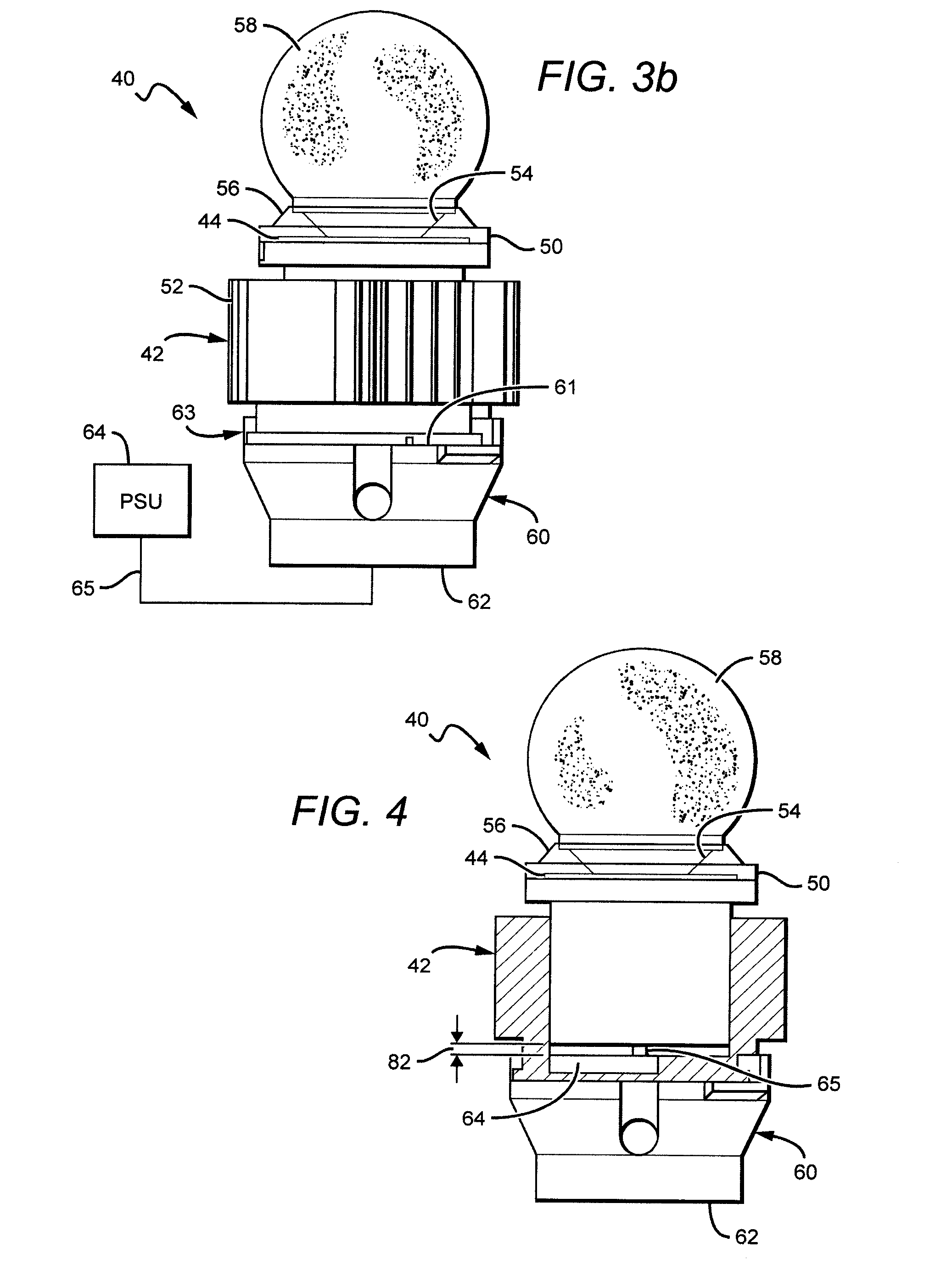
Bulbs with Edison or GU type sockets are used for electrical connection and do not provide an efficient heat dissipation path.
LED based light bulbs are now commercially available, but very few offer uniform light distribution patterns comparable to conventional light bulbs.
The light bulbs with emission patterns approaching those of conventional light bulbs can suffer from inadequate heat dissipation arrangements.
This heat dissipation arrangement can be very limiting and can result in sufficient thermal dissipation being strongly dependent upon the drive signal to the LEDs, and the bulb or fixture orientation.
These heat dissipation limitations can reduce the lifetime of LED light emitter(s) and can prevent the use of power levels necessary to allow for replacement of 60, 75 and 100 W incandescent bulbs.
Of these LED bulbs that approach and exceed 60 W incandescent equivalent light output, the heat sink temperature can become elevated (e.g. 75° C. or higher) which can also significantly reduce the lifetime of the power supply components, such as the electrolytic capacitors and diodes.

Method used


Image

  • Compact high efficiency remote LED module
  • Compact high efficiency remote LED module
  • Compact high efficiency remote LED module

Examples


Embodiment Construction

[0045]The present invention is directed to different embodiments of LED module structures that are efficient, reliable and cost effective, and provide an essentially omnidirectional emission pattern from directional LED light sources, such as forward emitting light sources. The different module structures can be used alone or in conjunction with a fixture to produce the desired emission. The present invention is also directed to lamp fixtures utilizing LED modules according to the present invention to provide for improved thermal management. The LED module and lighting fixture structures are arranged to provide for reliable and efficient light emission at elevated emission intensities, with some embodiments emitting from 800 to 1100 lumens or more in an omnidirectional emission pattern. This allows for the modules according to the present invention to be used for 60 and 75 W incandescent replacement applications, with some embodiments also being used for 100 W or higher replacements...


PUM


Abstract

Solid state modules and fixtures comprising different combinations and arrangements of a light source, one or more wavelength conversion materials, thermally conductive connection adapters allowing dissipation of heat outside of the module, and a remote power supply unit. This arrangement allows for greater thermal efficiency and reliability while employing solid state lighting and providing emission patterns that are equivalent with ENERGY STAR® standards. Some embodiments additionally place compensation circuits, previously included with power supply units, on the optical element itself, remote from the power supply unit. Various embodiments of the invention may be used to address many of the difficulties associated with utilizing efficient solid state light sources such as LEDs in the fabrication of lamps or bulbs suitable for direct replacement of traditional incandescent bulbs or fixtures using bulbs.

Description

[0001]This application claims the benefit of U.S. Provisional Patent Application Ser. No. 61 / 339,516, filed on Mar. 3, 2010, U.S. Provisional Patent Application Ser. No. 61 / 339,515, filed on Mar. 3, 2010, U.S. Provisional Patent Application Ser. No. 61 / 386,437, filed on Sep. 24, 2010, U.S. Provisional Patent Application Ser. No. 61 / 434,355, filed on Jan. 19, 2011, U.S. Provisional Patent Application Ser. No. 61 / 435,326, filed on Jan. 23, 2011, U.S. Provisional Patent Application Ser. No. 61 / 435,759, filed on Jan. 24, 2011, and U.S. Provisional Patent Application Ser. No. 61 / 502,224, filed on Jun. 28, 2011.BACKGROUND OF THE INVENTION[0002]1. Field of the Invention[0003]This invention relates to solid state lamps and modules and in particular to efficient and reliable light emitting diode (LED) based lamps and modules capable of producing omnidirectional emission patterns.[0004]2. Description of the Related Art[0005]Incandescent or filament-based lamps or bulbs are commonly used as li...

Claims


Application Information

Patent Timeline
Patent Type & Authority Applications(United States)
IPC IPC(8): F21V9/16F21V29/00F21V13/02H05B44/00
CPCF21K9/135F21K9/56F21V23/023H05B33/0803F21V29/89F21V3/04F21V23/008F21V29/75F21V29/773F21S8/033F21K9/232F21K9/64H05B45/357
Inventor LETOQUIN, RONANGUSCHL, PETERIBBETSON, JAMESTARSA, ERICTONG, TAOYUAN, ZONGJIEKELLER, BERND
Owner CREE INC
Why Eureka
Try Eureka