System of electrospray ion generator

a technology of electrospray and ion generator, which is applied in the field of analytical instruments, can solve the problems of no substantial improvement in ion transmission efficiency and inability to obtain steady ion emission, and achieve the effects of high ionization probability, steady ion emission and high efficiency

Inactive Publication Date: 2013-01-10
ZHEJIANG HAOCHUANG BIOTECH CO
View PDF3 Cites 10 Cited by
  • Summary
  • Abstract
  • Description
  • Claims
  • Application Information

AI Technical Summary

Benefits of technology

[0009]Against existing technical shortcomings, the present invention proposes a highly efficient, rationally designed, structurally simple instrument with high ionization probability and steady ion emission.
[0010]The objective of the present invention is to provide a rationally designed, structurally simple ESI source with high ionization probability and steady ion emission.
[0011]The objective of the present invention is realized by the application of the following technical scheme: It includes hollow capillary emission needle; emission needle brackets which...

Problems solved by technology

However, all of these prior inventions put the emission needle of the ESI source in the air.
As the ion flow and the liquid flow are closely related, steady ion emiss...

Method used


Image

  • System of electrospray ion generator
  • System of electrospray ion generator
  • System of electrospray ion generator

Examples


example 1

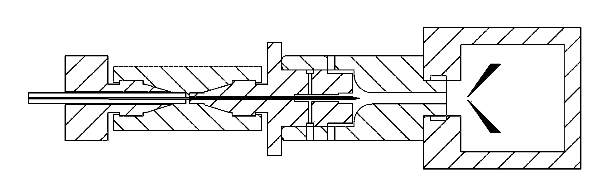
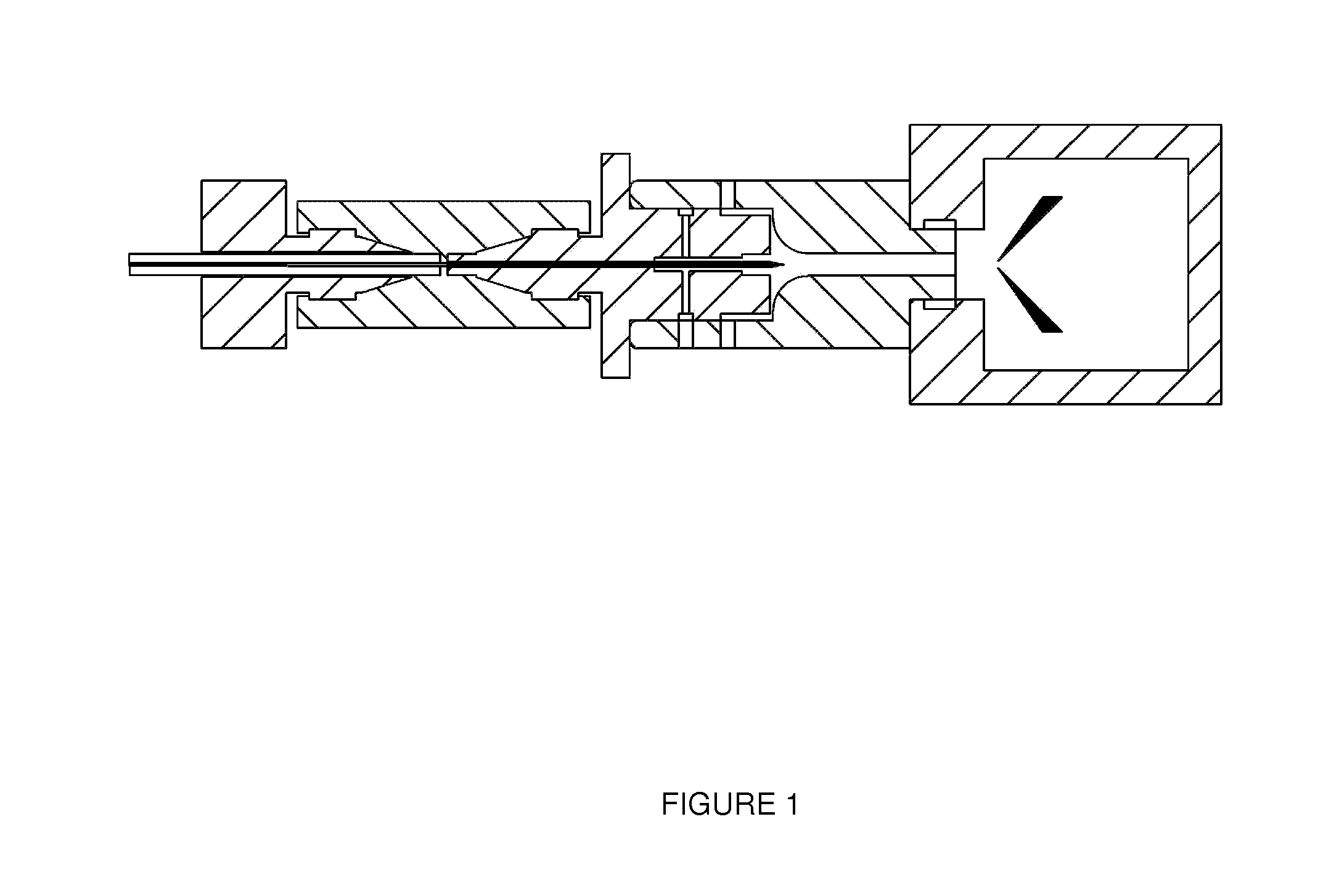
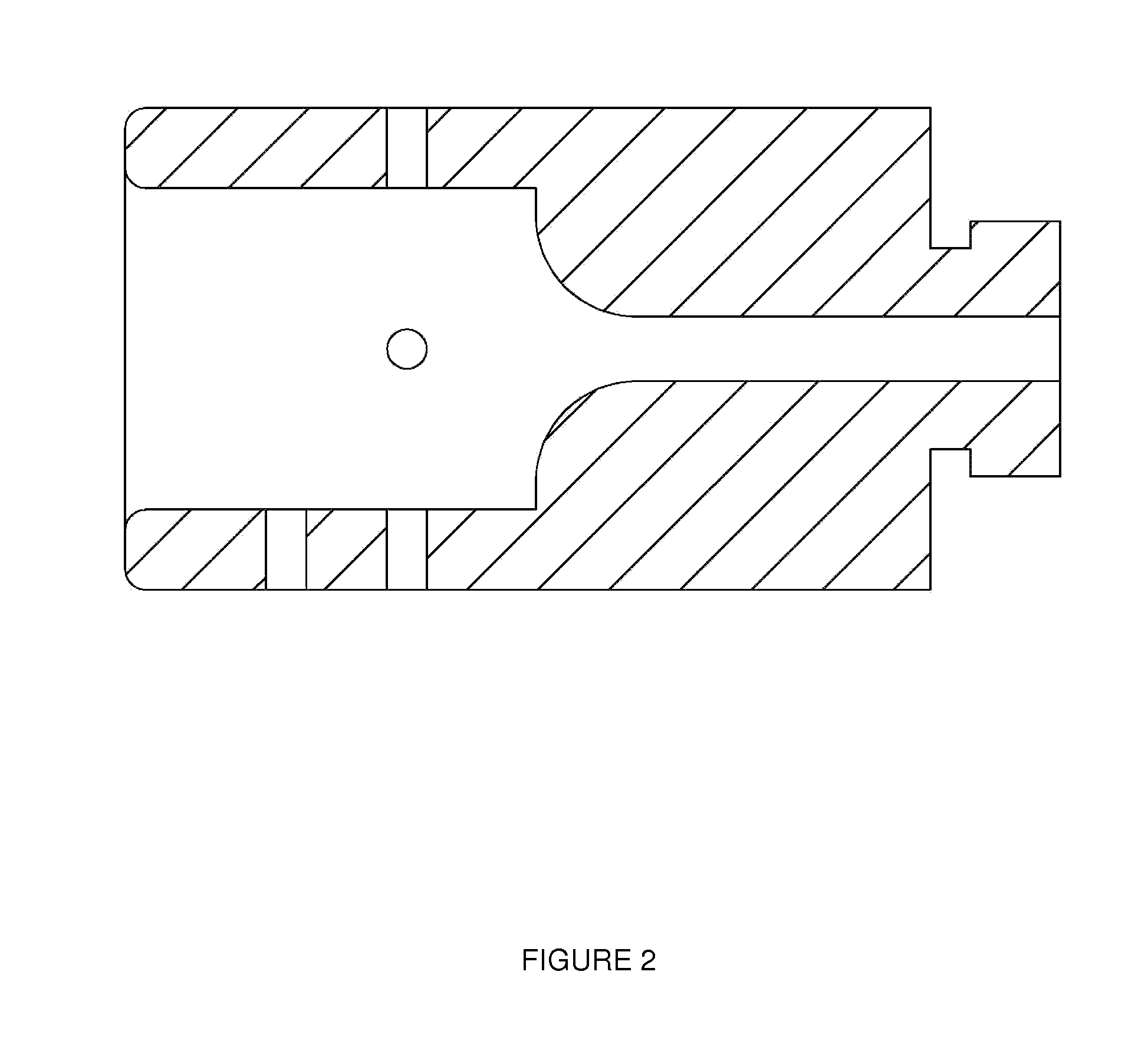
[0066]Based on the structure demonstrated by FIG. 1, FIG. 2, FIG. 4 and FIG. 5, an ESI generator is made, including the hollow capillary emission needle, HV terminal, hollow capillary emission needle bracket, one edge of the fixed block located on the cavum forepart of the HV terminal, and there is a through-hole in the middle of the fixed block; liquid chromatography connecting pipe runs through the through-hole in the fixed block and is fixed in the HV terminal, and the exterior wall of the liquid chromatography connecting pipe fits well the interior wall of the through-hole of the fixed block; the vacuum lead-in capillary connects the HV terminal through the hollow capillary emission needle bracket whose one edge is embedded into the cavum of the HV terminal and whose other edge is embedded into the cavum of the vacuum lead-in capillary, forming connection; the middle of the hollow capillary emission needle bracket is a through cavum, the diameter at the forepart cavum embedded w...

example 2

[0074]Given the same structure as in Example 1, there are auxiliary bores in the side of the vacuum lead-in capillary, the auxiliary bores run through the cavum; there are four auxiliary bores in the side of the vacuum lead-in capillary, gas which runs through auxiliary bores is nitrogen; the hollow capillary emission needle point goes beyond the end plane of the hollow capillary emission bracket by 2 mm; the hollow capillary emission needle is hollow glass capillary; the vacuum lead-in capillary is metal material, then the hollow capillary emission needle, the vacuum lead-in capillary, liquid chromatograph connection pipe, the vacuum lead-in capillary, the HV terminal and the hollow capillary emission bracket are put on the same axis; the rear cavum diameter of the hollow capillary emission bracket is 1.3 times the diameter of the hollow capillary emission needle; liquid chromatograph flow is 50 ml / min, sample size is 100 femtomoles, sample is Sigma's Angiotensin III, mass spectrum...

example 3

[0075]Given the same structure as in Example 1, there are auxiliary bores in the side of the vacuum lead-in capillary, the auxiliary bores run through the cavum; there are eight auxiliary bores in the side of the vacuum lead-in capillary, gas which runs through auxiliary bores is air; the hollow capillary emission needle point goes beyond the end plane of the hollow capillary emission bracket by 5 mm; the hollow capillary emission needle is hollow metal capillary; the vacuum lead-in capillary is ceramic material, then the hollow capillary emission needle, the vacuum lead-in capillary, liquid chromatograph connection pipe, the vacuum lead-in capillary, the HV terminal and the hollow capillary emission bracket are put on the same axis; the rear cavum diameter of the hollow capillary emission bracket is 1.4 times the diameter of the hollow capillary emission needle; liquid chromatograph flow is 200 nl / min, sample size is 50 femtomoles, sample is US Michrom's enzymolysis bovine albumin,...


PUM


Abstract

This invention relates to an analytical instrument field, specifically an instrument for pharmaceutical micromolecular and biological macromolecular ion generation. By this invention, through a hollow capillary emission needle and an emission needle bracket, the emission needle bracket forms a forward moving laminar flow gas surrounding the emission needles, eliminating the capillary counter-flow effect outside the capillary for liquid flowing out of the hollow capillary emission needle and pushing liquid forward; and vacuum lead-in capillary whose entrance is a specially designed arc mechanism, makes zero air flow speed in any direction, and the entrance happens to be the exit of the hollow capillary emission needle so as to ensure steady Taylor cone on the tip edge and ultimately obtains steady ion flow within a large flow range. This invention has advantages of steady ion emission and high ion transmission efficiency, and can be widely applied in the ion source preparation.

Description

BACKGROUND OF THE INVENTION[0001]1. Field of the Invention[0002]The present invention relates to an analytical instrument field, specifically an instrument for pharmaceutical micromolecular and biological macromolecular ion generation.[0003]2. Description of the Related Art[0004]It has been two decades since John B. Fenn, one of the laureates of Nobel Prize in Chemistry for 2002, applied Electrospray Ion (ESI) source to macromolecular mass spectrometry in the mid 1980s, but the ESI source mechanism still stays in two models: Ion Evaporation Model (IEM) and Charged Residue Model (CRM). The basic structure of ESI source has no essential difference with that in the 1990s.[0005]The basic structure of ESI source is filling a hollow metal or glass capillary tube with liquid against the ion inlet of the mass spectrum, applying positive or negative high voltage to the liquid, wherein positive and negative ions are formed in the atmosphere, and the vacuum system of the mass-spectrograph abso...

Claims


Application Information

Patent Timeline
IPC IPC(8): H01J27/26H01J49/16
CPCB05B5/0255H01J49/16H01J49/167G01N30/7266
Inventor ZHU, YIXINLU, TINGTING
Owner ZHEJIANG HAOCHUANG BIOTECH CO
Why Eureka
Try Eureka