Method for separating cells, cell culture substrate, and device for separating cells

a cell culture substrate and cell technology, applied in the field of separating cells, can solve the problems of cell adhesion factor or extracellular matrix damage by enzyme treatment, cell damage, etc., and achieve the effect of good precision and without adversely affecting these target cells

Active Publication Date: 2013-01-24
NAT INST OF ADVANCED IND SCI & TECH
View PDF6 Cites 9 Cited by
  • Summary
  • Abstract
  • Description
  • Claims
  • Application Information

AI Technical Summary

Benefits of technology

[0028]According to the present invention, because the active energy rays are irradiated onto only a partial region of the cell culture substrate, the acidic substance acts upon only the cells within that region.
[0029]Accordingly, the target cells can be separated with good precision, without adversely affecting these target cells.
[0030]The present invention is useful in the fields of cellular engineering, regenerative medicine, bio-related industry and tissue engineering.

Problems solved by technology

Accordingly, in the techniques described above, the cell adhesion factor or the extracellular matrix may be damaged by the enzyme treatment, or the cell may be damaged by the ultrasound.

Method used


Image

  • Method for separating cells, cell culture substrate, and device for separating cells
  • Method for separating cells, cell culture substrate, and device for separating cells
  • Method for separating cells, cell culture substrate, and device for separating cells

Examples


example 1

[0164]A solution containing the compound (1) (NAI-106, manufactured by Midori Kagaku Co., Ltd.) was applied to the surface of a substrate composed of polystyrene and then dried to form a layer containing the compound (1), and a gelatin layer was then formed on top. This yielded a cell culture substrate 1 having a layer containing the compound (1) and a gelatin layer provided on top of the surface of the substrate.

[0165]The surface of the substrate 1 was inoculated with MDCK cells across the entire surface of the substrate.

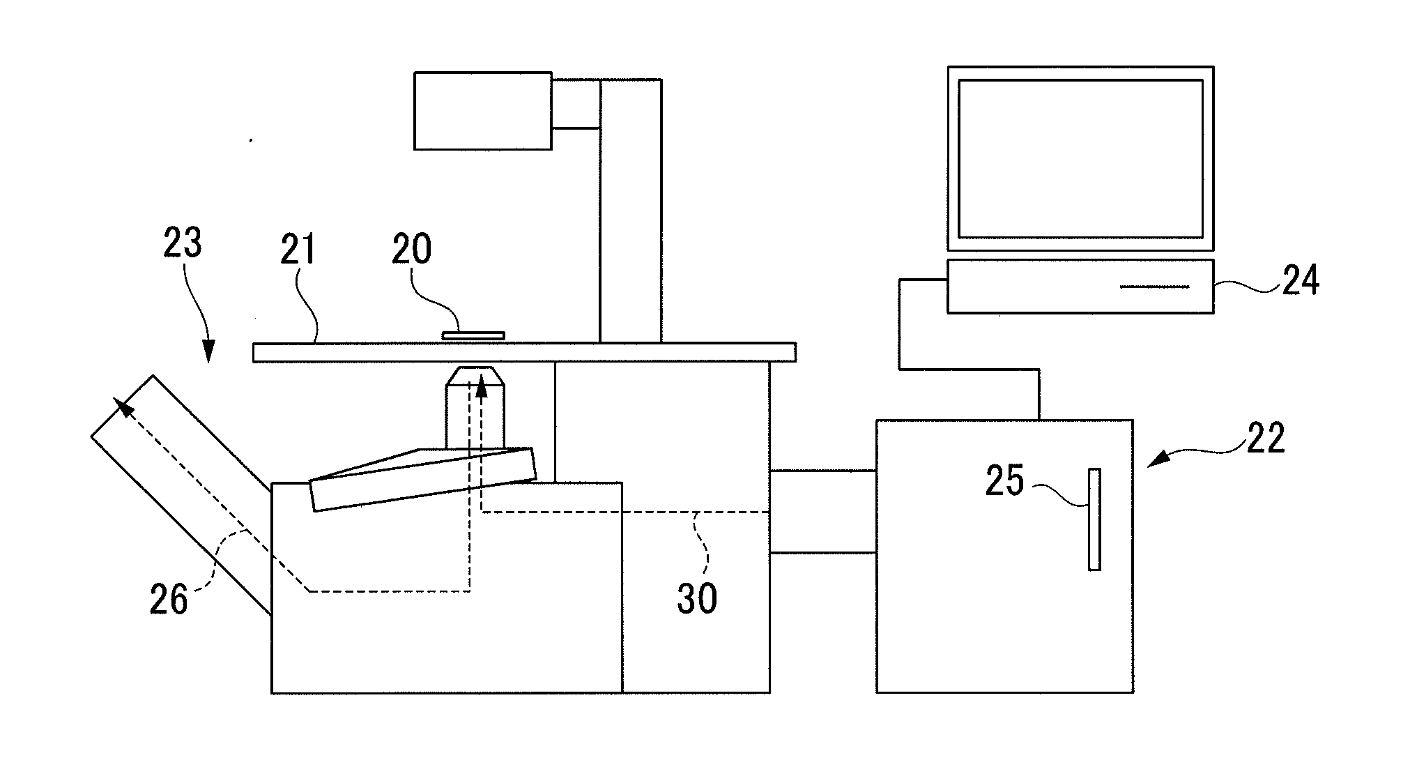
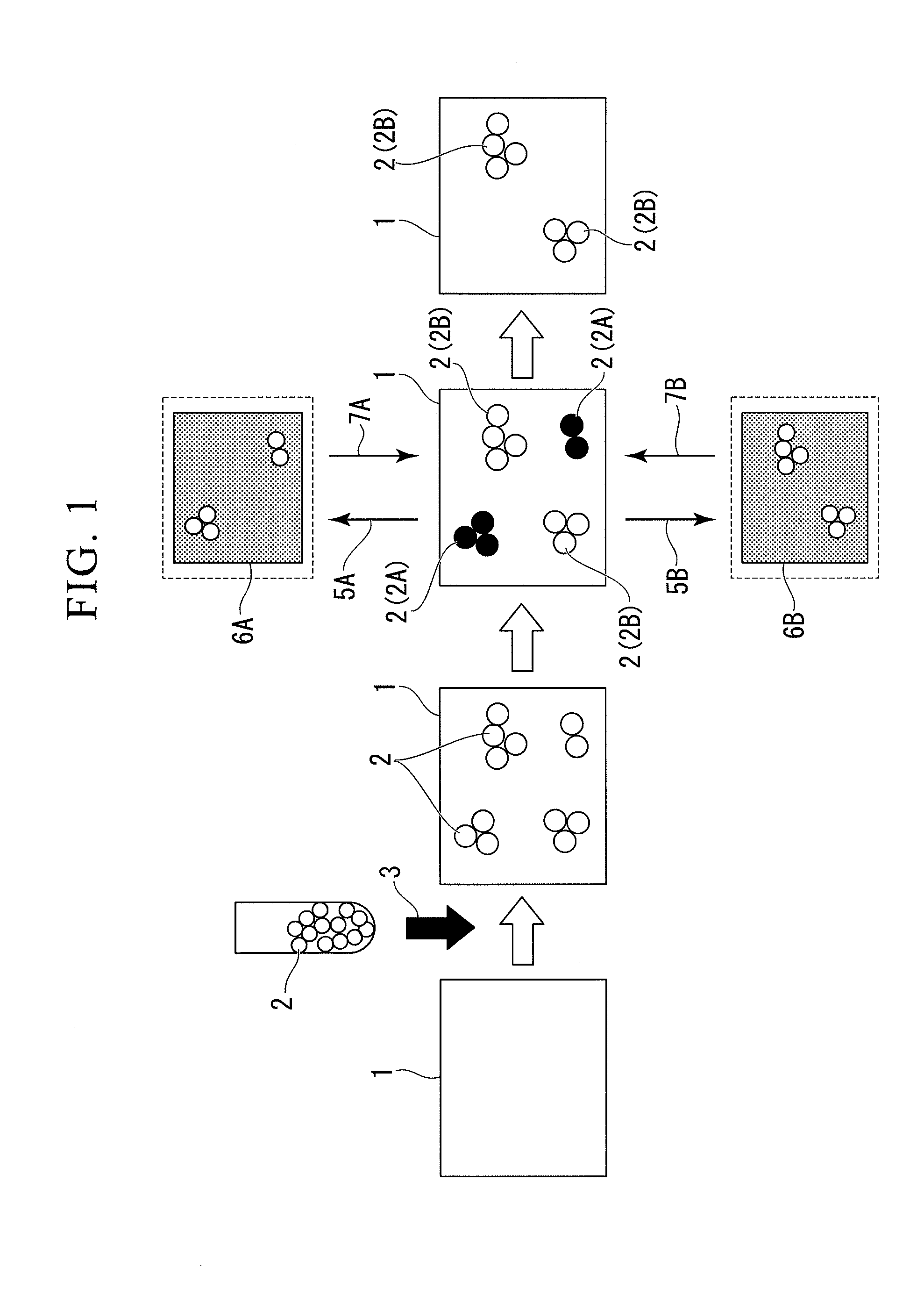
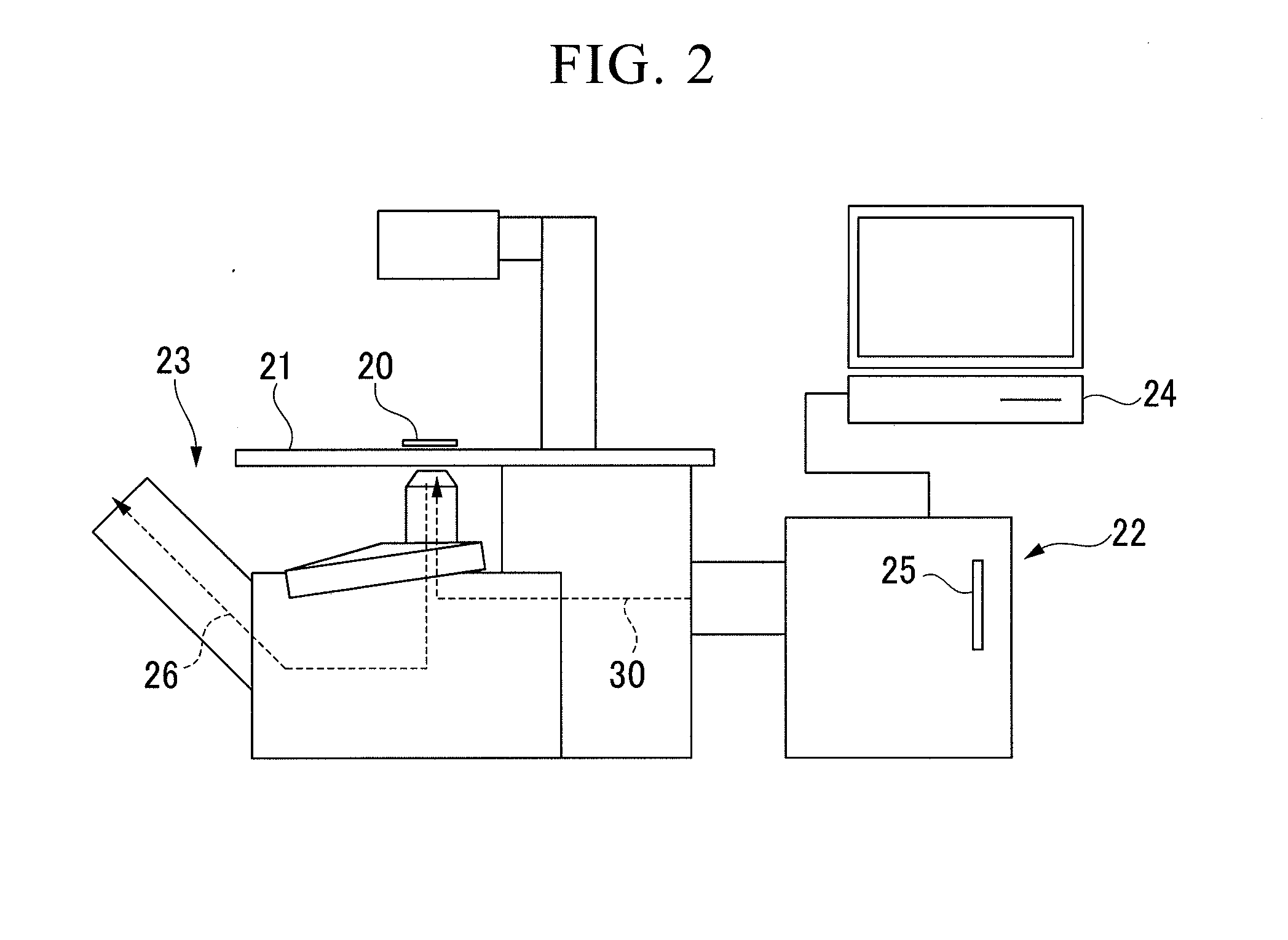
[0166]Subsequently, ultraviolet rays (wavelength: 365 nm) were irradiated (irradiation energy: 6 J / cm2) onto only a partial region of the substrate 1 (see FIG. 1), while the substrate 1 was observed using a microscope 23 illustrated in FIG. 2.

[0167]The results of performing Live / Dead staining, which fluorescently stains live cells green and dead cells red, confirmed that only the cells within the irradiated region were killed.

examples 2 to 4

[0168]A cell culture substrate 1 having a layer composed of PMMA containing the compound (1) on the surface of the substrate was inoculated with one type of cell selected from among MDCK cells (example 2), Hek293 cells (example 3) and NIH / 3T3 cells (example 4), and ultraviolet rays (wavelength: 365 nm) were then irradiated onto only a partial region of the cell culture substrate. The remaining conditions were the same as those described for the example 1.

[0169]The results of performing Live / Dead staining confirmed that only the cells within the irradiated region were killed.

examples 5 and 6

[0170]A cell culture substrate 1 having a layer composed of PMMA containing the compound (2) on the surface of the substrate was inoculated with one type of cell selected from among CHO-K1 cells (example 5) and NIH / 3T3 cells (example 6), and a visible light (wavelength: 436 nm) was then irradiated onto only a partial region of the cell culture substrate. The remaining conditions were the same as those described for the example 1.

[0171]The results of performing Live / Dead staining confirmed that only the cells within the irradiated region were killed.


PUM

PropertyMeasurementUnit
pKaaaaaaaaaaa
wavelengthaaaaaaaaaa

Abstract

A method for separating cells which includes: adhering cells to the surface of a cell culture substrate containing a photo-acid generator that generates an acidic substance upon irradiation with active energy rays, and irradiating only a partial region of the cell culture substrate with the active energy rays to selectively remove the cells within the partial region, thereby separating the cells within the partial region and cells in other regions.

Description

TECHNICAL FIELD[0001]The present invention relates to a method for separating cells such as animal cells, a cell culture substrate used in the method, and a cell separation device. Priority is claimed on Japanese Patent Application No. 2010-086132, filed Apr. 2, 2010, the content of which is incorporated herein by reference.BACKGROUND ART[0002]Examples of cell separation techniques include flow cytometry (FACS: fluorescence-activated cell sorting) and magnetic-activated cell sorting systems (MACS).[0003]These methods are effective in separating and collecting floating cells such as leukocytes and lymphocytes, but when applied to the separation and collection of anchorage-dependent cells, the anchorage-dependent cells that have adhered to the substrate must first be converted to a floating state, by an enzyme treatment using trypsin or the like, or by physical detachment of the cells using an ultrasonic nozzle.[0004]Accordingly, in the techniques described above, the cell adhesion fa...

Claims


Application Information

Patent Timeline
Patent Type & Authority Applications(United States)
IPC IPC(8): C12N13/00C12N1/00C12N5/04C12M1/42C12N5/07
CPCC12M23/20C12M25/06C12N13/00C12M47/04C12N1/02C12M33/00
Inventor SUMARU, KIMIOTAKAGI, TOSHIYUKIKIKUCHI, KYOKOSATO, TAKUYAMAGUCHI, MANAEKANAMORI, TOSHIYUKI
Owner NAT INST OF ADVANCED IND SCI & TECH
Why Eureka
Try Eureka