
Magnetic stimulation having a freely selectable pulse shape

a free-selectable, pulse-shaped technology, applied in the direction of thyristor, semiconductor devices, therapy, etc., can solve the problems of low field energy, coil very quickly overheat, and inability to generate efficient single monophasic rectangular pulses having direct (dc) components. , to achieve the effect of stimulating nerves, low field energy, and field strength

Active Publication Date: 2013-01-31
TECH UNIV MUNCHEN
View PDF3 Cites 88 Cited by
  • Summary
  • Abstract
  • Description
  • Claims
  • Application Information

AI Technical Summary

Benefits of technology

The present invention provides a device and method for inducing nerve stimulation using low field energy and field strength. This reduces the necessary energy for stimulation, which in turn requires a lower coil voltage, simplifies safety measures, and reduces heat losses. The device and method also require a low coil current for triggering the stimulation, which enables the use of smaller power circuit components and reduces electronic power losses. Additionally, the invention allows for efficient and flexible generation of magnetic field pulses with high performance and low losses. The pulses can be shaped to optimize the charging and discharging of nerve fibers, resulting in reduced field strength and energy requirements. Overall, the invention has applications in repetitive and portable settings, as well as in home-care and mobile applications.

Problems solved by technology

Therefore, no efficient single monophasic rectangular pulses having a direct (DC) component can for example be generated as they are used in the electrical stimulation.
However, for the inductive magnetic stimulation, this detour through the magnetic field of the coil also causes important technical problems:
Therefore, the pulse sources are technically complex; furthermore the coil very quickly overheats due to the current heat losses, where it must presently be additionally considered that the coil may not reach too high temperatures as it is a component that can directly contact the body.
Since for these devices, the pulse energy of the magnetic field is completely lost with each pulse, these devices have particularly high energy consumption.
These first devices were therefore not suitable for so-called repetitive stimulation for which 10 to 50 pulses per second are required.
Furthermore, also the size of the devices and their high price make it difficult to open new fields of application.
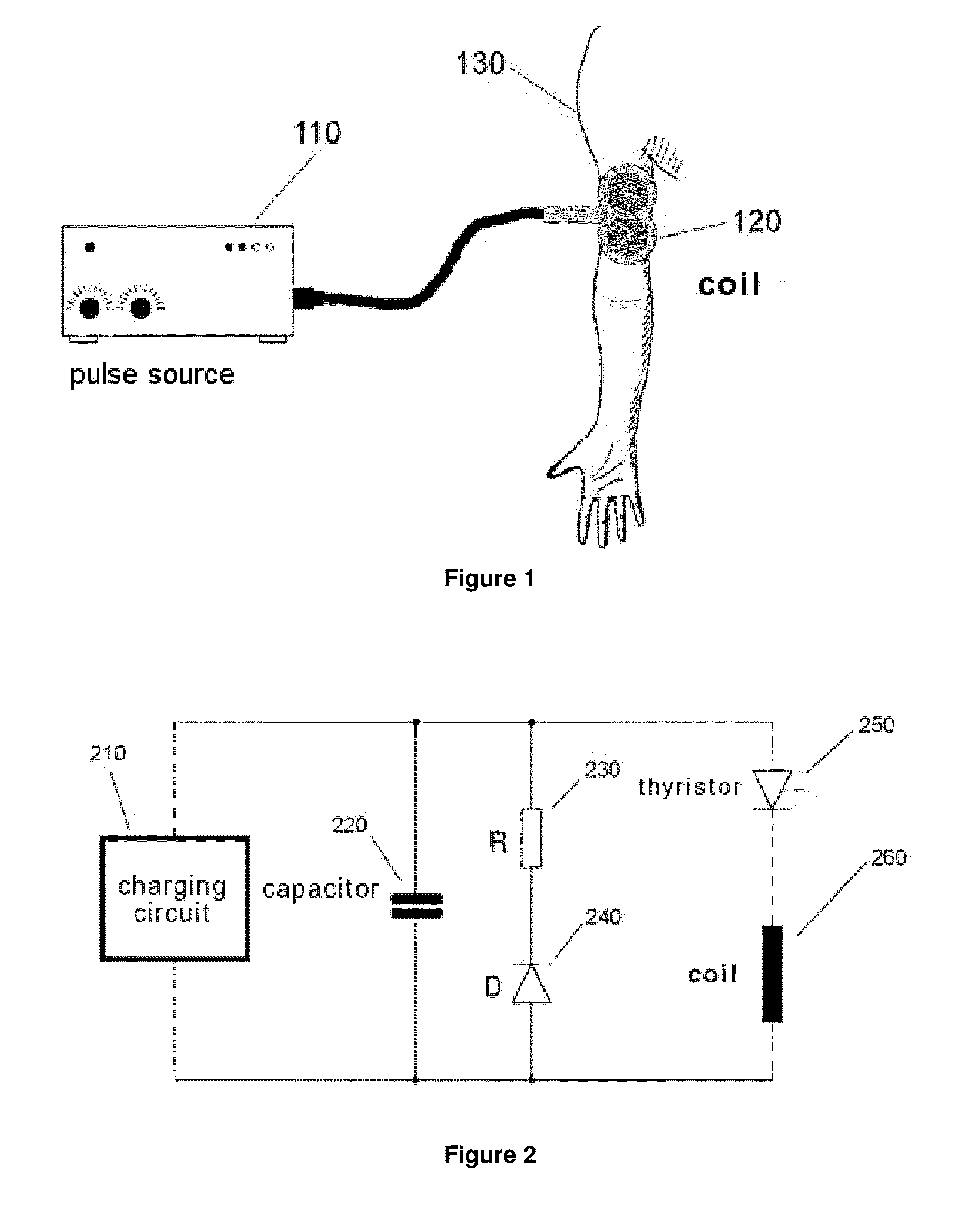
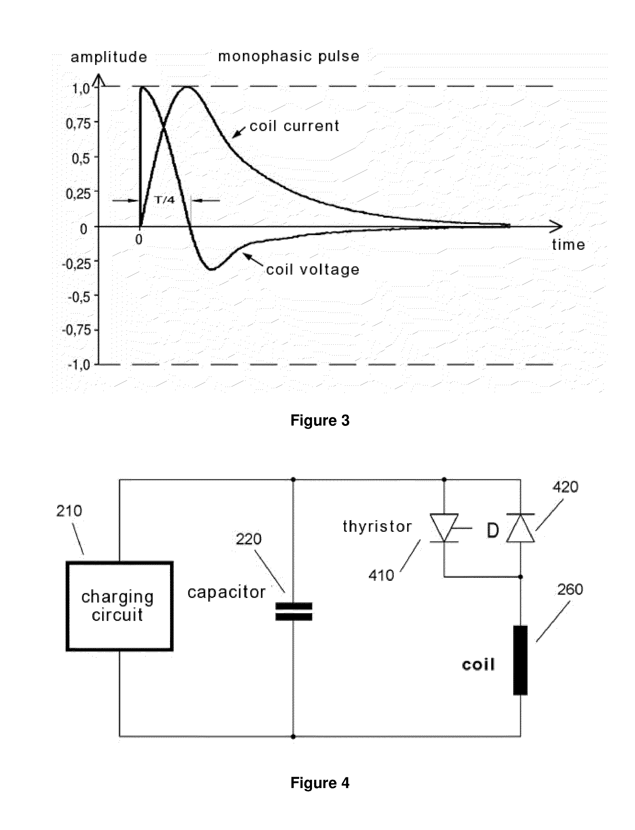
The losses of the circuit of FIG. 4 mainly result via the ohmic resistances of the circuit components involved and their connection cables.
It is disadvantageous with the biphasic half-wave stimulation, however, that after the pulse, the voltage direction in the capacitor is inverted compared with the state prior to the pulse discharge, making the respective charging circuit more complex.
However, especially for this repetitive operation, energy consumption and coil heating is still considerable.
However, the electrical resistance of the coil cannot be reduced arbitrarily for weight reasons.
Therefore, the previously used devices also have the great disadvantage that the pulse duration depends on the inductance of the coil.
In particular, for example, small coils often have design-related lower inductance than large coils; therefore, the pulse duration with previous systems could not be kept constant in an optimal range when using different coils.
1, 2008) are either very energy inefficient or they lead to highly complex technical structures and are therefore too expensive for commercial technical realization
For all applications, the disadvantage, therefore, of inductive magnetic stimulation still is high energy consumption, very rapid overheating of the coil and high weight of the charging and pulse generating electronics.
Another disadvantage is that the temporal course of the stimulus pulse can not be individually flexibly adapted to certain nerve cell or axon types or other requirements.

Method used


Image

  • Magnetic stimulation having a freely selectable pulse shape
  • Magnetic stimulation having a freely selectable pulse shape
  • Magnetic stimulation having a freely selectable pulse shape

Examples


Embodiment Construction

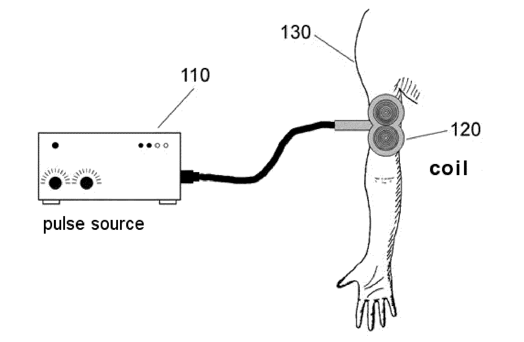
[0081]The invention is based on the finding that certain technical-physical parameters, which are required for the stimulation of nerve and muscle tissue, can be reduced significantly for inductive stimulation if the temporal course of the electric field induced in the body and the resulting currents are adapted to the dynamic behavior of ion transport in the nerve cell membrane. These parameters can, for example, be the required field energy, the coil loss energy, the required electric coil current, the required coil voltage, the maximum steepness of the coil voltage or the coil current, or the acoustic artifact of the coil.

[0082]Furthermore, the invention is based on the finding that the respective inductive stimulation devices must be able to generate different temporal courses of the current and the voltage during pulse delivery, in order to thereby fulfill the conditions for different optimization criteria.

[0083]FIG. 8 by way of example shows a very favorable temporal course of...


PUM


Abstract

Device and method for generating brief strong current pulses in a coil for generating magnetic field pulses which according to the electromagnetic induction principle induce stimulation currents in the body tissue triggering an action potential of the nerve and / or muscle cells, where the coil is positionable close to the body tissue to be stimulated so that its magnetic field passes through the body tissue, and where the device comprises a power generating unit that can generate a freely selectable temporal course of the current through the coil during the current pulse. A method for determining an optimized temporal course of a brief strong current pulse through the coil, where the temporal course of the current pulse is calculated using a method which numerically simulates the electrical behavior of nerve and / or muscle cells and the coil and optimizes the course of the current pulse regarding at least one parameter, or which by means of stimulating the nerve and / or muscle cells with predetermined current pulses optimizes the temporal course of the current pulse regarding at least one parameter and therefrom determines essential parameters of nerve and / or muscle cells.

Description

[0001]The present invention relates generally to a method and a device for stimulating nerve and muscle cells in the body tissue in accordance with the electromagnetic induction principle by means of brief strong magnetic field pulses being created by a coil. The invention further relates to electrical power circuits for generating freely selectable temporal courses of brief, strong current pulses through the coil to generate pulse-shaped magnetic fields for stimulating nerve and muscle cells.BACKGROUND OF THE INVENTION[0002]Generally, specific cells in the body tissue can be stimulated by electrical fields acting from the outside. Nerve or muscle cells can in particular be excited by depolarization of an axon or a bundle of fibers, respectively, stimulated by an external field, and the triggering of action potentials and the subsequent stimulus conduction resulting therefrom. This is done in that the electric fields cause electrical currents in the tissue, which in turn trigger act...

Claims


Application Information

Patent Timeline
Patent Type & Authority Applications(United States)
IPC IPC(8): A61N2/04
CPCA61N2/02A61N2/006H03K17/136
Inventor WEYH, THOMASGOTZ, STEFAN M.
Owner TECH UNIV MUNCHEN
Learn More