Arc pvd plasma source and method of deposition of nanoimplanted coatings

Active Publication Date: 2013-02-07
ENVAEROSPACE
View PDF6 Cites 7 Cited by
  • Summary
  • Abstract
  • Description
  • Claims
  • Application Information

AI Technical Summary

Benefits of technology

[0046]It is the objective of this invention to provide a method and an apparatus which allows for continually changing the structure of the applied film by nanoimplanting atoms, molecules, compounds or

Problems solved by technology

Engine power begins to deteriorate rapidly leading t

Method used


Image

  • Arc pvd plasma source and method of deposition of nanoimplanted coatings
  • Arc pvd plasma source and method of deposition of nanoimplanted coatings
  • Arc pvd plasma source and method of deposition of nanoimplanted coatings

Examples


Embodiment Construction

[0091]The present invention employs an apparatus which within one process provides a continuously changing structure of the applied film.

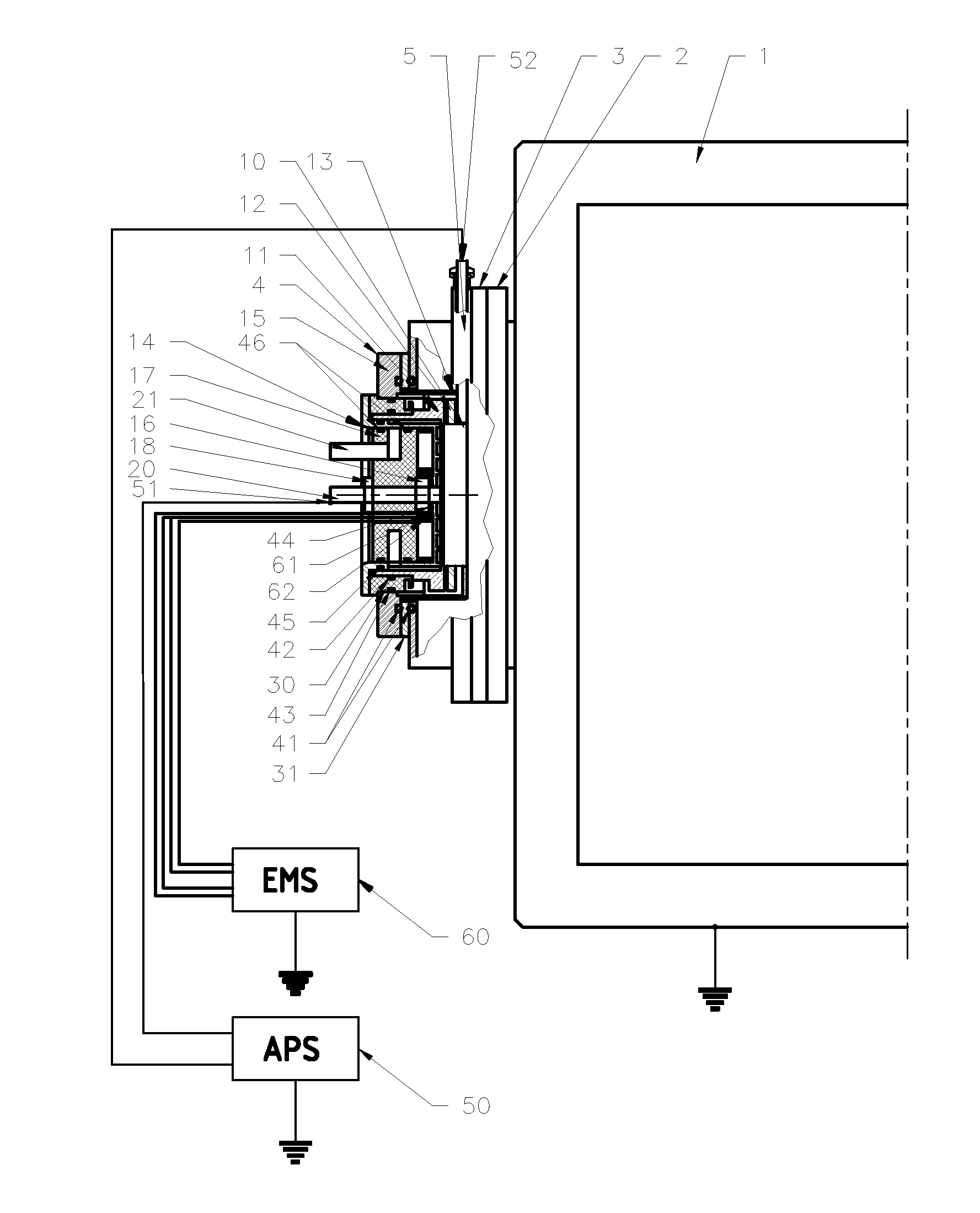
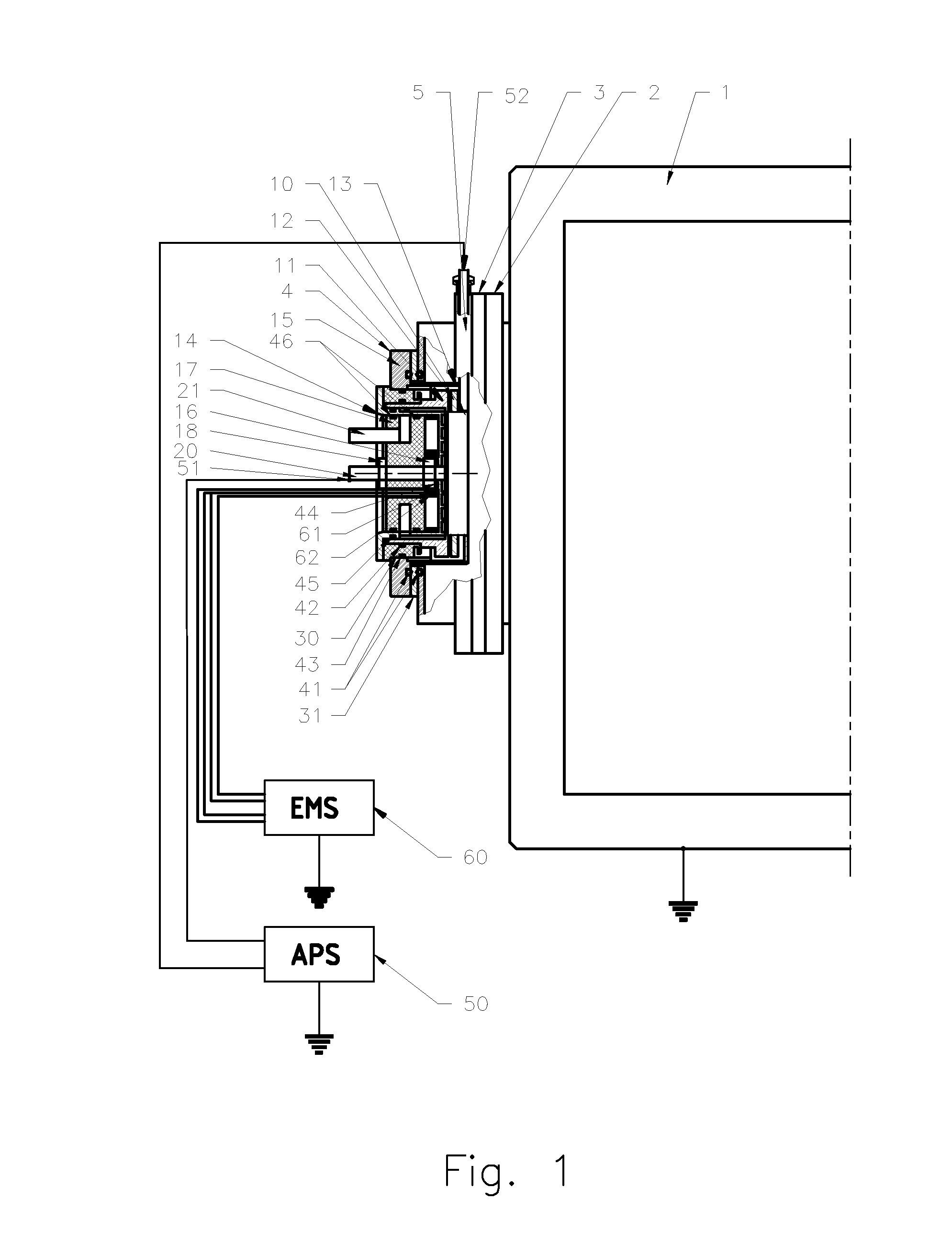
[0092]FIG. 1 presents a cathodic arc physical vapor deposition system which contains: a vacuum processing chamber 1, an arc source 4 with an Arc Power Supply (APS) 50, a chamber evacuation system, a gas supply system, a substrate holding device, a bias voltage supply and a process control system.

[0093]The arc source 4 is assembled to an anode 5, insulated from the anode 5 by an insulator 31 and sealed from vacuum by o-rings 41. The anode 5 is fixed to a chamber flange 2. The anode 5 is insulated from the chamber 1 by an insulator 3. The arc source 4 contains a flange 15 which through an insulator 30 is supporting a cathode holder 11. A cathode 10 is held by the cathode holder 11 and locked by a holding ring 12. The cathode holder 11 is isolated from the vacuum by o-rings 42 and 43. The cathode 10 is shielded by a cover 13. The cathode holder 11 and...


PUM

PropertyMeasurementUnit
Forceaaaaaaaaaa
Magnetic fieldaaaaaaaaaa
Structureaaaaaaaaaa

Abstract

The invention relates to a method and an apparatus for applying metallic, ceramic or composite thin film coatings onto parts, components and tools (e.g. gas turbine engine compressor blades or cutting tools) by a cathodic arc deposition technique. The method and the apparatus allows for a continually changing structure of the applied film by nanoimplanting atoms, molecules, compounds or other chemical species and structures of different materials thus coating a substrate during a single process. Furthermore, during the same process it allows for creating a coating with specific parameters as required. For instance: hardness, smoothness, corrosion resistance, erosion resistance.

Description

CROSS-REFERENCE TO RELATED APPLICATIONS[0001]Provisional Patent Application No.: 61 / 514,445, filed on Aug. 2, 2011.BACKGROUND OF THE INVENTION[0002]The present invention relates to an arc source for a cathodic arc physical vapor deposition system. The cathodic arc vacuum evaporation technique is used to deposit metallic, ceramic and composite coatings on the following; cutting tools, punching and forming tools and injection molding tools. It is further applied in optical and decorative applications, medical tools and implants, automotive and aerospace industries. It's becoming widely used in aircraft, generators and tank gas turbines.[0003]Each of these applications requires different coating properties. Parameters like: yield strength, toughness, hardness, adhesion, surface roughness, wear resistance, corrosion resistance and erosion resistance have to be specifically chosen, the coating is then designed based on those requirements.[0004]For example helicopter turbine engine compre...

Claims


Application Information

Patent Timeline
IPC IPC(8): C23C14/24B82Y40/00
CPCC23C14/325H01J37/34H01J37/32055C23C14/35H01J37/32614H01J37/3408H01J37/345H01J37/3452H01J37/3455H01J37/3458
Inventor WARZYSZYNSKI, MARIUSZ
Owner ENVAEROSPACE
Why Eureka
Try Eureka