System and Method for High-Frequency Amplifier

a high-frequency amplifier and low-noise technology, applied in amplifiers, amplifiers with semiconductor devices/discharge tubes, electrical devices, etc., can solve the problems of difficult to match the input and output of inductive coupling, difficult to embed squid-based amplifiers in traditional transmission line environments, and difficult to match traditional squid-based amplifiers within transmission lines. achieve the effect of improving the signal-to-noise ratio, simple modeling at microwave frequencies, and easy integration into low-i

Active Publication Date: 2013-02-21
WISCONSIN ALUMNI RES FOUND
View PDF2 Cites 38 Cited by
  • Summary
  • Abstract
  • Description
  • Claims
  • Application Information

AI Technical Summary

Benefits of technology

[0009]The present invention overcomes the aforementioned drawbacks by providing a system and method for a low-noise, phase-insensitive linear amplifier capable of accommodating readout signals from quantum computing applications, even when such signals reach frequencies in the RF and microwave range. The amplifier can significantly improve the signal-to-noise ratio in delicate measurements of microwave signals or other high-frequency signals associated with, for e

Problems solved by technology

Although approaches employing SQUID are, in principle, capable of amplifying signals at frequencies approaching the Josephson frequency (typically in the tens of GHz), it remains challenging to embed the SQUID in a traditional transmission line environment.
Accordingly, it is challenging to utilize a traditional SQUID-based amplifier within a transmission line environment because it is difficult to match the inductive coupling input and the output of a SQUID-based amplifier to common transmission line environments.
For example, the inductive coupling input of the SQUID-based amplifier presents not only an obvious inductive component but also substantial parasitic reactance.
Modeling and accounting for these characteristics of the SQUID-based amplifier can be challenging, particularly, when the input signal is a weak microwave tone employed as a dispersive probe of the quantum state of a superconducting or semiconducting qubit.
Using traditional amplifier designs, such as SQUID-based designs, it can be challenging to provide for efficient coupling of an RF or microwave signal to the device.
For example, the parasitic capacitance of the SQUID-based amplifier

Method used


Image

  • System and Method for High-Frequency Amplifier
  • System and Method for High-Frequency Amplifier
  • System and Method for High-Frequency Amplifier

Examples


Embodiment Construction

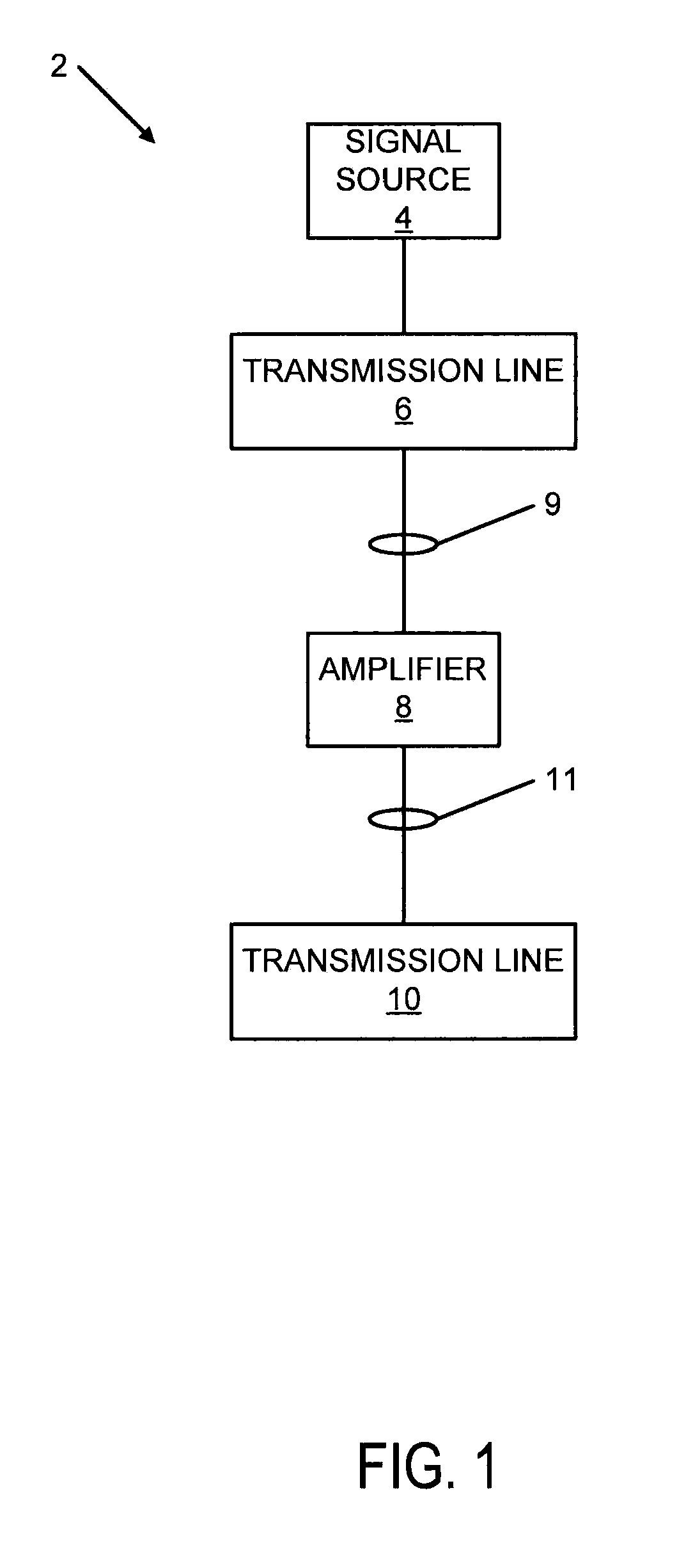
[0043]Referring to FIG. 1, a schematic, block diagram is provided illustrating an exemplary device architecture incorporating the present amplifier system. System 10 includes signal source 4. Signal source 4 may include a high-frequency signal source in the range of RF or microwave (in one example, a signal having a frequency between approximately 1-10 GHz). The high-frequency signal source 4 may be a quantum computing device or another source of high-frequency communication signals, such as those found in satellite or space-based applications.

[0044]Signal source 4 is connected to input transmission line 6. In one implementation, transmission line 6 is an approximately 50 or 75Ω transmission line. Transmission line 6 is directly connected to amplifier 8. The transmission line 6 being “directly” connected to the amplifier 8, as will be described, refers to the transmission line 6 being connected to an integrated input matching network of the amplifier; this input network in turn has ...


PUM


Abstract

A system and method for operating an amplifier system is provided. The amplifier system includes an input providing a direct coupling configured to receive a high-frequency input signal having a frequency in at least one of a radiofrequency (RF) and microwave range. The amplifier system also includes an amplifier including a dielectric material separating at least two superconducting layers forming an amplifier loop configured to receive the high-frequency input signal and deliver an amplified signal. The amplifier system includes an output providing a direct coupling configured to deliver the amplified signal.

Description

CROSS-REFERENCE TO RELATED APPLICATIONS[0001]N / AFIELD OF THE INVENTION[0002]The invention relates to a system and method for a high-frequency amplifier and, more particularly, to a system and method for a low-noise phase insensitive high-frequency amplifier.BACKGROUND OF THE INVENTION[0003]The rapid development of superconducting quantum electronics has motivated a search for quantum-limited amplifiers for the low-noise readout of qubits and linear cavity resonators. Conventional approaches have relied upon dc Superconducting QUantum Interference Devices (dc SQUID) that can achieve noise performance approaching the fundamental quantum limit imposed on phase-insensitive linear amplifiers—namely, the amplifier adds at least half a quantum of noise to the signal it amplifies.[0004]Although approaches employing SQUID are, in principle, capable of amplifying signals at frequencies approaching the Josephson frequency (typically in the tens of GHz), it remains challenging to embed the SQUI...

Claims


Application Information

Patent Timeline
IPC IPC(8): H03F1/00
CPCH03F2200/534H03F3/195
Inventor MCDERMOTT, ROBERT FRANCISHOVER, DAVIDRIBEILL, GUILHEM JEAN-ANTOINECHEN, YUNG-FU
Owner WISCONSIN ALUMNI RES FOUND
Why Eureka
Try Eureka