Method for the production of a conformal element, a conformal element and uses of the same

a technology of conformal elements and production methods, applied in the direction of sustainable manufacturing/processing, tactile signalling systems, instruments, etc., can solve the problems of non-uniform shielding performance, affecting the effective performance of the circuit, and affecting the effect of the shielding performance, so as to achieve the effect of broadening the scope of applications

Inactive Publication Date: 2013-02-28
CANATU OY
View PDF7 Cites 15 Cited by
  • Summary
  • Abstract
  • Description
  • Claims
  • Application Information

AI Technical Summary

Benefits of technology

[0078]The advantage of the present invention relies on e.g. the properties of the formable element comprising at least one layer of a HARMS-network. As discussed above a layer of HARMS-network is flexible and formable enabling the formable element to be conformally arranged by e.g. thermoforming onto a three-dimensional surface. The three-dimensionality of e.g. the touch and / or proximity sensitive film broadens the scope of applications where to implement touch and / or proximity based functions.

Problems solved by technology

The disturbance may interrupt, obstruct, or otherwise degrade or limit the effective performance of the circuit.
Drawback of the prior art shield is that it has not been possible to arrange a conformal shield on a structure to be protected, for example, against electromagnetic radiation.
Non-conformal EM-shields, such as traditional Faraday Cages, may cause non-uniformities in the shielding performance which may be difficult to take into account when designing the shield.
In addition, traditional non-conformal shieldings, such as metal cages, are expensive to manufacture and integrate, take up significant space and are rigid.
The problem with prior art techniques is, in many applications, the difficulty of forming conformal films or elements.
However, the problem with prior art techniques is that it has not been possible to produce truly flexible or conformal touch sensitive films.
In general, prior art techniques do not allow producing truly flexible or conformal elements on three-dimensional surfaces.

Method used


Image

  • Method for the production of a conformal element, a conformal element and uses of the same
  • Method for the production of a conformal element, a conformal element and uses of the same
  • Method for the production of a conformal element, a conformal element and uses of the same

Examples


example 1

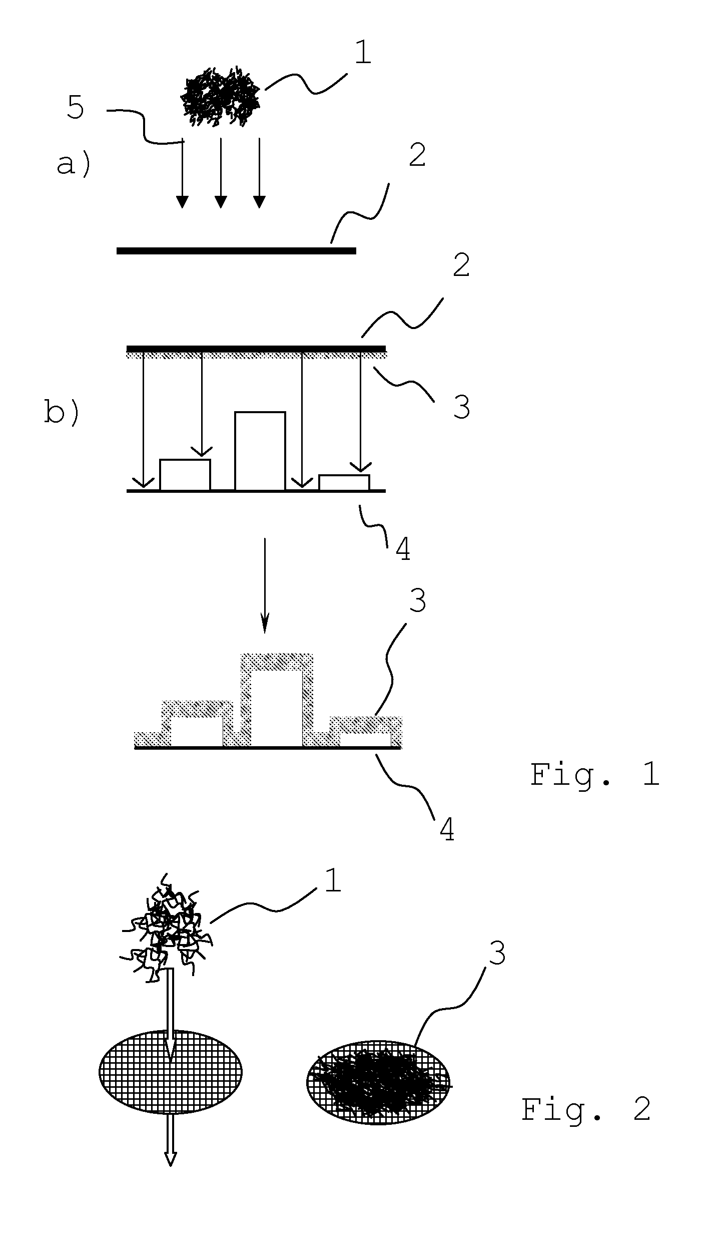
[0098]As an example of how to deposit a network of HARM-structures onto the formable substrate, thus forming an formable element, according to one embodiment of the present invention, SWCNTs (single walled carbon nanotubes) were synthesized in an aerosol laminar flow (floating catalyst) reactor using carbon monoxide and ferrocene as a carbon source and a catalyst precursor, respectively.

[0099]SWCNTs were then collected directly from the gas phase downstream of the reactor by filtering through a 2.45 cm diameter nitrocellulose (or silver) disk filter (Millipore Corp, USA). The filter, in this embodiment, takes the role of a formable substrate. The deposition temperature on the filter surface was measured to be 45° C. The layer thickness of SWCNT networks formed on the substrate was controlled by the deposition time, which could be altered from a few seconds to several hours depending on the desired network thickness. Measurement results showed that the deposits were randomly oriented...

example 2

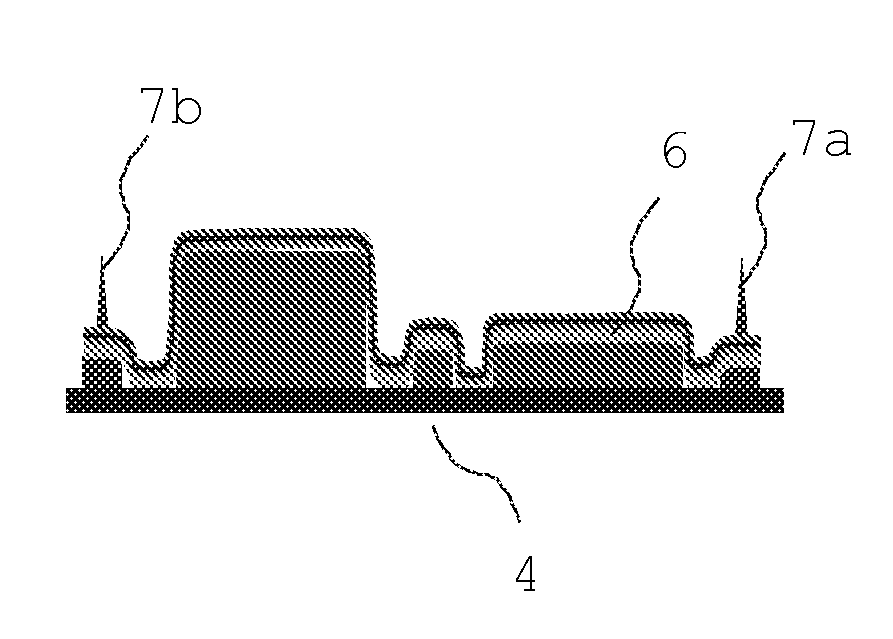
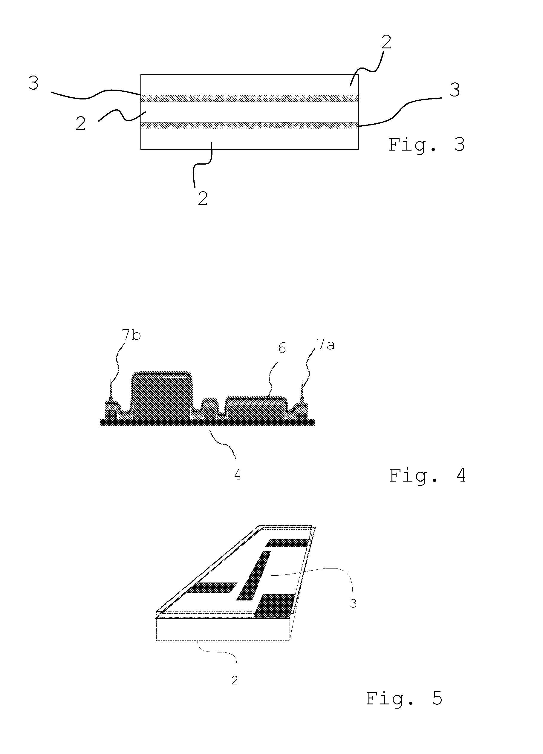
[0101]In accordance with the present invention a structure, for example, to be shielded against electromagnetic radiation can comprise an element comprising a multilayer structure arranged in a conformal manner onto said structure. The multilayer structure can comprise a number of networks of HARM-structures sandwiched between, for example, a number of polymer substrates, to enhance the shielding compared to a single network of HARM-structures. Said multilayer element can for example comprise a second network of HARM-structures on top of a first polymer substrate having thereon arranged a first network of HARM-structures on the other side against the structure to be shielded. This multilayer element comprises thus a first network of HARM-structures on one side of the first polymer substrate and the second network of HARM-structures on the other side of the first polymer substrate. On the second network of HARM-structures can further be a second polymer substrate, in which case the s...

example 3

[0103]In accordance with the present invention a thermoacoustic speaker is manufactured, in which a conductive network of HARM-structures on a PET substrate is thermocompressed over a compound curved glass surface. Electrodes are attached and the speaker is attached to an output jack of an amplifier to drive the speaker.


PUM

PropertyMeasurementUnit
transparentaaaaaaaaaa

Abstract

The invention relates to a method for the production of an at least partially electrically conductive or semi-conductive element on a structure, wherein the element comprises one or more layers, the method comprising the steps of a) forming a formable element comprising one or more layers, wherein at least one layer comprises a network of high aspect ratio molecular structures (HARM-structures), wherein the HARM-structures are electrically conductive or semi-conductive, and b) arranging the formable element in a conformal manner onto a structure by pressing and/or vacuum sealing the formable element on a three-dimensional surface of the structure, for producing a conformal and at least partially electrically conductive or semi-conductive element comprising one or more layers, wherein at least one layer comprises a network of HARM-structures, on the three dimensional surface of the structure. Further, the invention relates to a conformal element and uses thereof.

Description

FIELD OF THE INVENTION[0001]The invention relates to a method for the production of an at least partially electrically conductive or semi-conductive element on a structure. Further, the invention relates to a conformal and at least partially electrically conductive or semi-conductive element on a structure. Further, the invention relates to uses of a conformal element.BACKGROUND OF THE INVENTION[0002]High aspect ratio molecular structures (HARM-structures) are of great interest due to their unique and useful physical and chemical properties. The high conductivity of certain HARM-structures, such as metallic carbon nanotubes, carbon NanoBuds, nanowires and nanoribbons, together with their extremely high aspect ratios allows for efficient electrical percolation, even in randomly oriented surface deposited mats or films. Networks including conducting HARM-structures are useful, for example, as the conductive channel of a transistor. Networks including semi-conducting HARM-structures ar...

Claims


Application Information

Patent Timeline
Patent Type & Authority Applications(United States)
IPC IPC(8): G08B6/00B32B37/10B32B37/14B82Y99/00
CPCB82Y30/00B82Y40/00G02F1/167G02F2001/133334G02F1/13338Y10T156/10H05K2201/0323H05K2201/0715Y02E10/50H01L31/0392H05K1/0216H01L31/035227Y02E10/549G06F3/041G02F1/133334Y02P70/50H01L21/02603H01L21/02606H10K85/221
Inventor BROWN, DAVID P.
Owner CANATU OY
Why Eureka
Try Eureka