
Micro-electro-mechanical systems (MEMS) device and method for fabricating the same

a micro-electro-mechanical and mechanical system technology, applied in the direction of instruments, semiconductor electrostatic transducers, fluid pressure measurement, etc., can solve the problems of sensitivity degradation, structure may not be easily fabricated, and distance cannot be reduced without restriction, so as to achieve the effect of improving capacitance without reducing the thickness of the mems capacitan

Active Publication Date: 2013-03-07
SOLID STATE SYST
View PDF1 Cites 63 Cited by
  • Summary
  • Abstract
  • Description
  • Claims
  • Application Information

AI Technical Summary

Benefits of technology

The patent describes a way to make a MEMS device that can have more capacitance without making its MEMS capacitance thicker. This means that the device can have more flexibility and be more effective at doing its job, without needing to be made thicker.

Problems solved by technology

However, the distance cannot be reduced without restriction.
If the distance d of gap of the MEMS capacitor is too small, the structure may be not easily fabricated.
The sensitivity is degraded and the output noise may also increase.
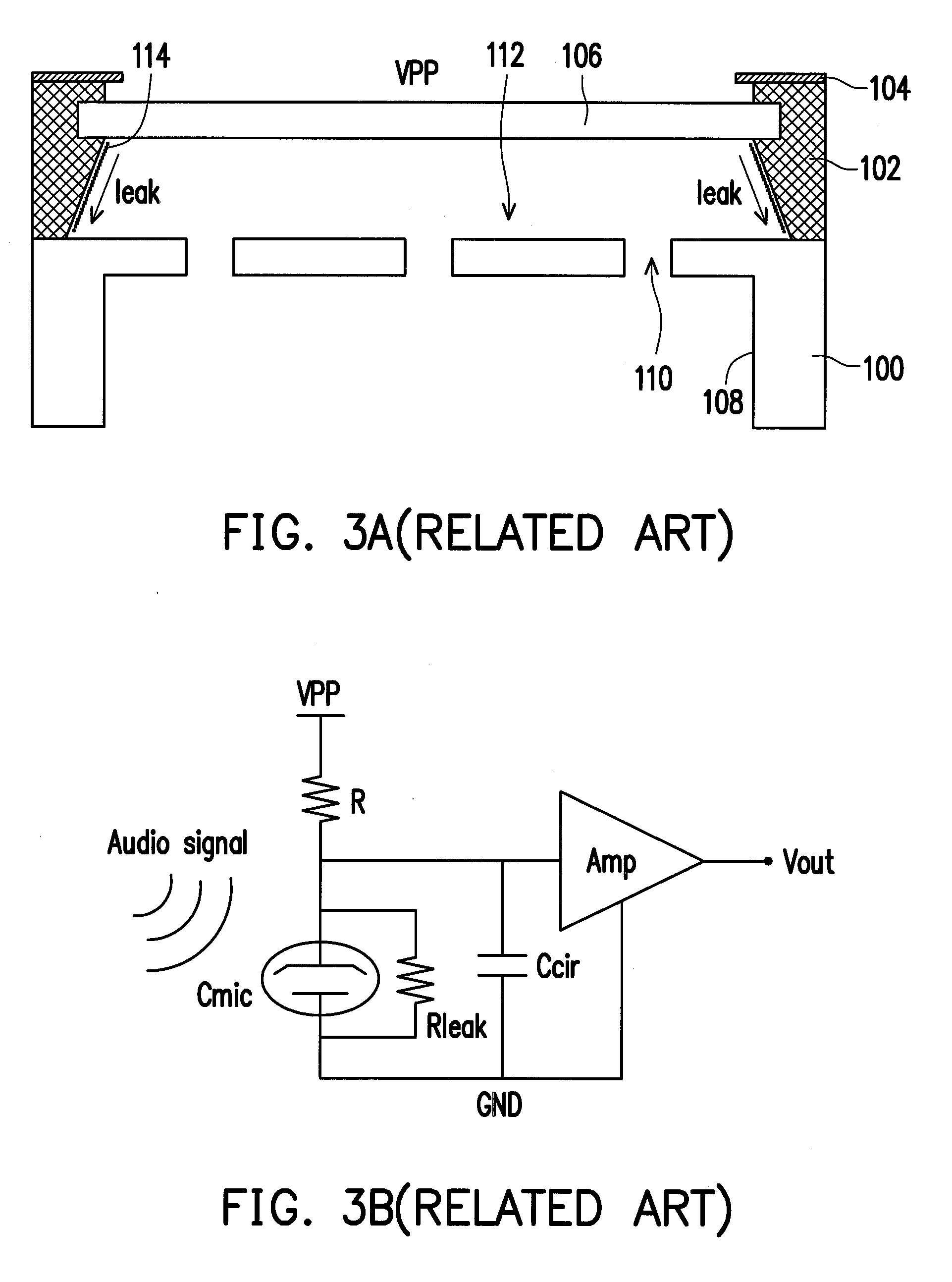
How to have high capacitance for the MEMS device without causing current leakage is still an issue to improve.

Method used


Image

  • Micro-electro-mechanical systems (MEMS) device and method for fabricating the same
  • Micro-electro-mechanical systems (MEMS) device and method for fabricating the same
  • Micro-electro-mechanical systems (MEMS) device and method for fabricating the same

Examples


Embodiment Construction

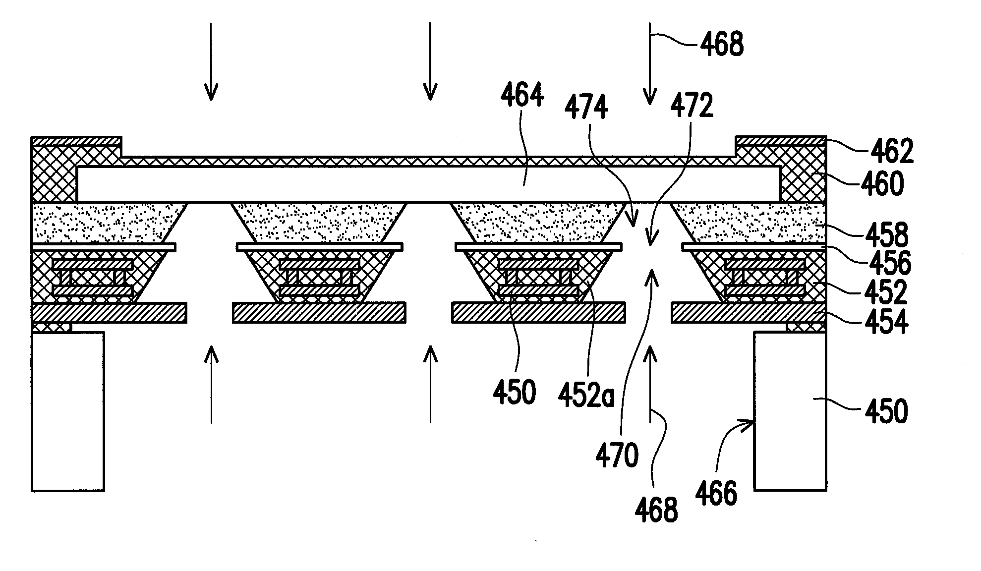
[0049]In the invention, a novel MEMS device is proposed, of which capacitance of the MEMS capacitor can be improved without reducing the thickness of the MEMS capacitor.

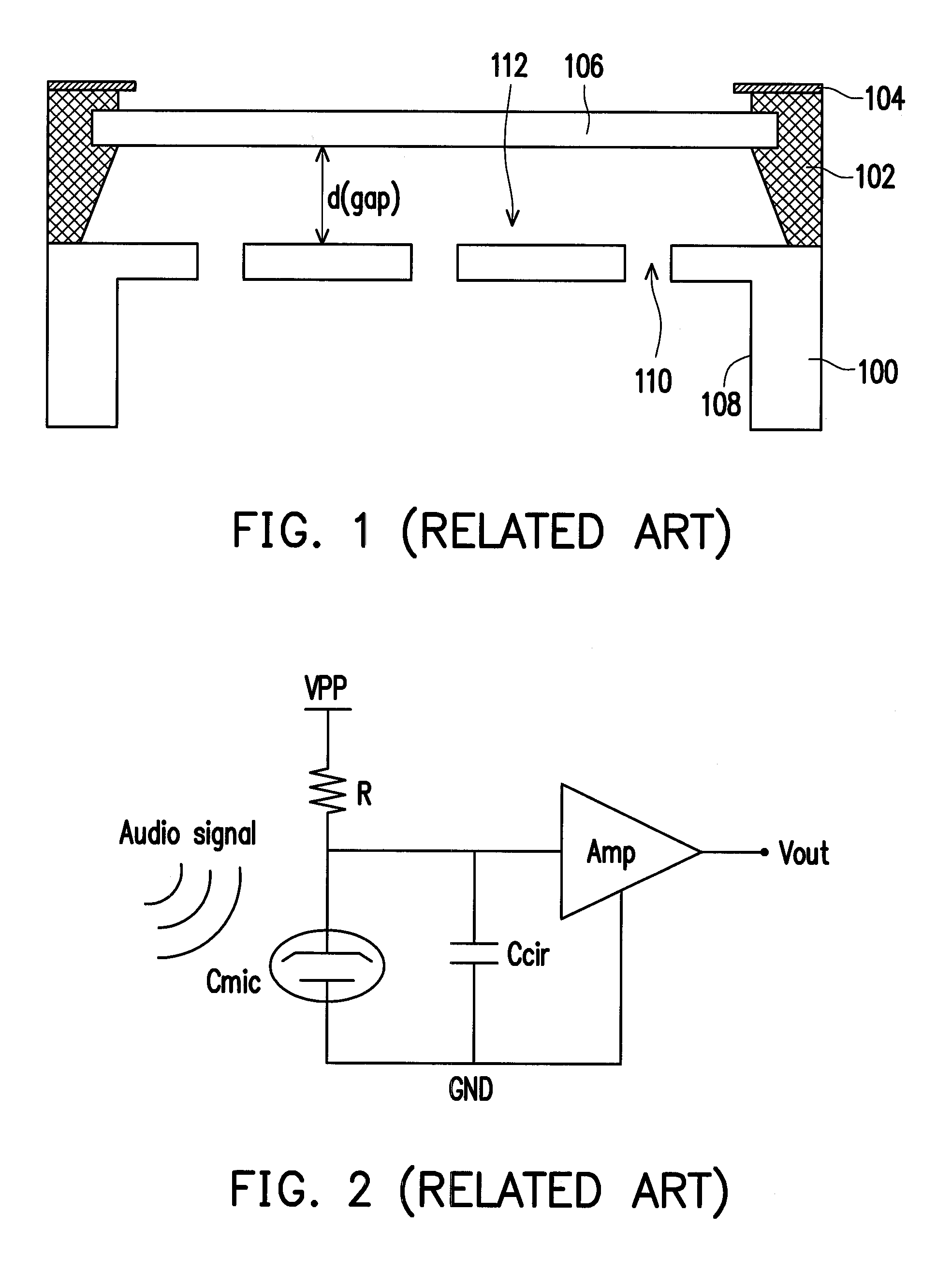
[0050]In considering the convention structure of MEMS device as for example shown in FIG. 1, the capacitance Cmic is satisfying:

Cmic=εair·A / d   (1).

[0051]It can be found that the capacitance Cmic may also be increased by increasing the effective dielectric constant. In this consideration, the air can be replaced by some dielectric material without changing the distance d, so as to increase the capacitance. In current semiconductor fabrication, the proposed semiconductor structure can be fabricated without the adding difficult process.

[0052]Several embodiments are provided to describe the present invention. However, the present invention is not just limited to the provided embodiments. In addition, the embodiments may also be properly combined to each other.

[0053]FIG. 4 is a cross-sectional structure, schematically il...


PUM

PropertyMeasurementUnit
dielectricaaaaaaaaaa
conductiveaaaaaaaaaa
sizeaaaaaaaaaa

Abstract

A MEMS device includes a substrate. The substrate has a plurality of through holes in the substrate within a diaphragm region and optionally an indent space from the second surface at the diaphragm region. A first dielectric structural layer is then disposed over the substrate from the first surface, wherein the first dielectric structural layer has a plurality of openings corresponding to the through holes, wherein each of the through holes remains exposed by the first dielectric structural layer. A second dielectric structural layer with a chamber is disposed over the first dielectric structural layer, wherein the chamber exposes the openings of the first dielectric structural layer and the through holes of the substrate to connect to the indent space. A MEMS diaphragm is embedded in the second dielectric structural layer above the chamber, wherein an air gap is formed between the substrate and the MEMS diaphragm.

Description

BACKGROUND OF THE INVENTION[0001]1. Field of Invention[0002]The present invention relates to Micro-Electro-Mechanical Systems (MEMS) device. More particularly, the present invention relates to the structure and fabrication method for MEMS device with improved sensing capability.[0003]2. Description of Related Art[0004]MEMS device, such as MEMS microphone, has been popular gradually due to the excellent features comparing to the conventional ECM microphone. The features of MEMS microphone includes: 1. thin and small size; 2. SMD (surface mountable device) indicating easy assembly with sold flow; 3. high stability and environmental resistance. However, in comparison with the IC package, the requirements of microphone package include receiving the sound pressure from acoustic signal, inducing mechanical motion and transferring to electrical signal. Therefore it needs an acoustic path to receive the sound pressure, a transducer to response the sound pressure, a sufficient back volume fo...

Claims


Application Information

Patent Timeline
Patent Type & Authority Applications(United States)
IPC IPC(8): H01L29/84H01L21/02
CPCH01G5/18B81C1/00682H04R19/04H04R19/005B81C1/00698
Inventor HSIEH, TSUNG-MINLEE, CHIEN-HSINGLIOU, JHYY-CHENG
Owner SOLID STATE SYST
Learn More