Process for producing tubular ceramic structures

a technology of ceramic structures and processes, applied in the direction of cell components, final product manufacturing, sustainable manufacturing/processing, etc., can solve the problems of limiting the usefulness of extrusion methods for tubular ceramic structures, and each of these techniques for producing tubular ceramic structures is subject to certain inherent drawbacks and/or limitations, etc., to achieve precise predetermined dimensional tolerances, reduce size, and easily and conveniently vary or modify

Active Publication Date: 2013-03-07
WATT FUEL CELL CORP
View PDF8 Cites 26 Cited by
  • Summary
  • Abstract
  • Description
  • Claims
  • Application Information

AI Technical Summary

Benefits of technology

[0013]d) heat shrinking the mandrel component of the mandrel-tubular ceramic structure assembly to cause the mandrel to undergo shrinkage to a reduced size in which the external surface of the mandrel separates from the interior surface of the tubular ceramic structure facilitating removal of the mandrel therefrom.
[0015]Another advantage of the process herein for producing a tubular ceramic structure is its capability for readily and conveniently varying, or modifying, the ceramic-forming composition along the length of the structure. Ceramic-forming formulations of differing composition can be readily applied in a controlled manner to the external surface of the rotating mandrel at different rates and / or at different times during the production process. The degree of separation or blending of different ceramic-forming formulations during the production process can also be carefully controlled employing calibrated dispensing equipment known in the art to provide tubular ceramic products with enhanced performance capabilities compared with tubular products made by other fabrication techniques such as extrusion and dip coating.

Problems solved by technology

Each of these techniques for producing tubular ceramic structures generally, and tubular components of SOFCs in particular, is subject to certain inherent drawbacks and / or limitations.
This practical requirement tends to limit the usefulness of extrusion methods to the production of relatively thick-walled tubular ceramic structures.
The requirement for a relatively thick-walled extrudate, which can only be achieved with an extrudable material of fairly high viscosity, e.g., one of paste- or putty-like consistency, imposes yet another limitation on the usefulness of extrusion methods for the manufacture of tubular ceramic structures, namely, the need to carefully and completely dry the extrudate before subjecting it to such high temperature downstream processes as the burning out of organics (i.e., residual solvent(s), dispersant(s), binder(s), etc.) and sintering.
Too rapid drying and / or insufficient drying can result in the production of mechanical defects in the extrudate before and / or after carrying out either or both of the aforementioned high temperature post-extrusion processes.
Still another limitation of the extrusion technique is its inability to readily vary the composition of the extruded tube, e.g., to alter the composition of the tube in one preselected location but not in another.
In the case of dip coating, the requirement that the ceramic-forming composition be applied to a tubular substrate generally limits this technique to the production of structures in which the substrate becomes an integral, functional component of the final article.
This requirement for a tubular substrate necessarily restricts the type as well as the design of those devices that can utilize a tubular ceramic article produced by the dip coating technique.
Moreover, it is difficult in practice to provide tubular ceramic structures with relatively thin walls and / or with walls of uniform thickness employing dip coating.

Method used


Image

  • Process for producing tubular ceramic structures
  • Process for producing tubular ceramic structures
  • Process for producing tubular ceramic structures

Examples


example

[0069]A green state tubular anode is produced possessing the following dimensions: length of 230 mm, outside diameter of 6.35 mm and wall thickness of 0.50 mm.

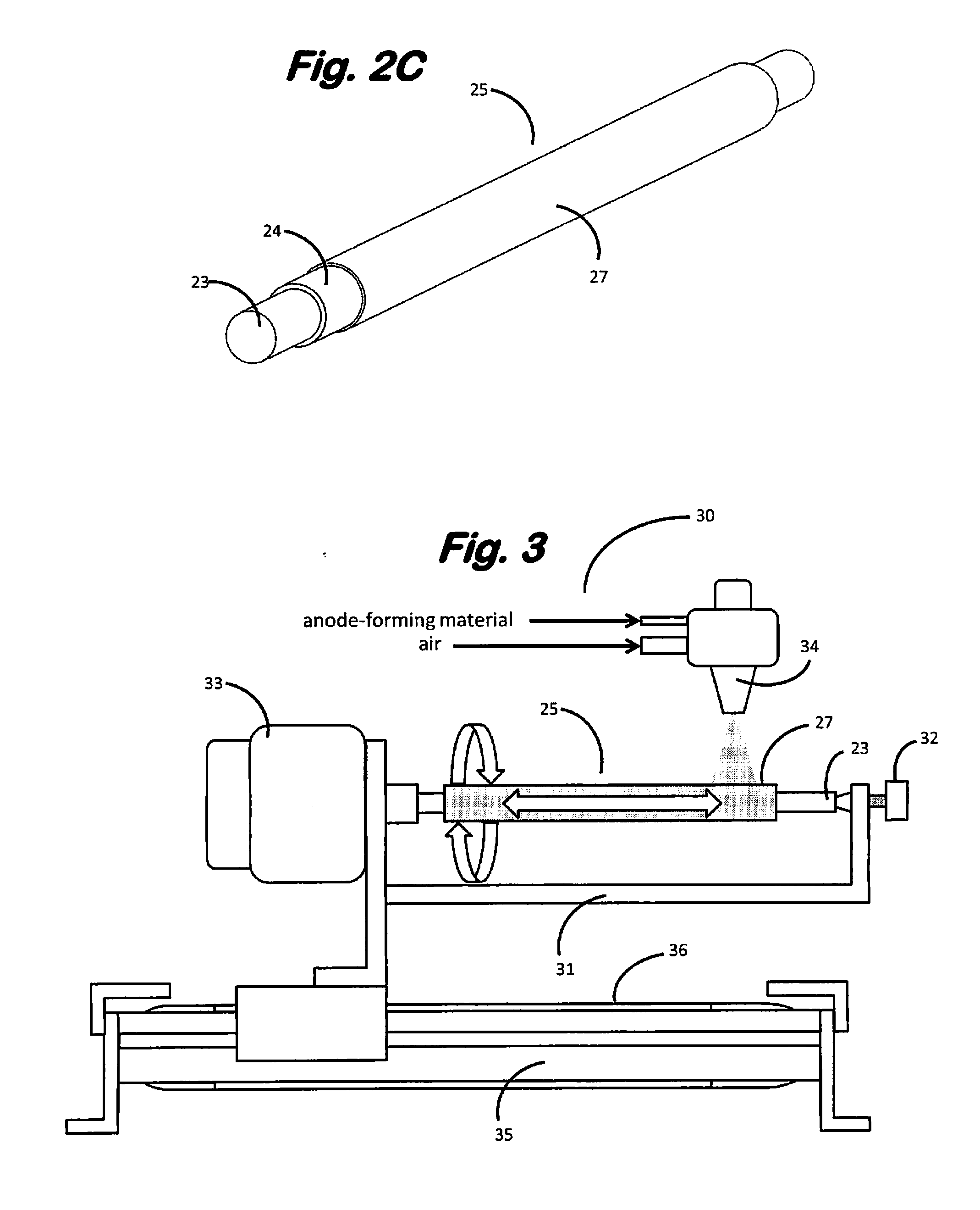
[0070]An anode-forming composition in the form of organic solvent slurry is provided by combining the following ingredients in the indicated amounts:

ComponentAmount (g)8-mol % yttrium zirconium oxide powder2.10NiO powder3.90methylethylketone (MEK)10.0polyvinylpyrrolidone (PVP) powder2.00

[0071]The tubular anode is produced from the foregoing anode-forming composition employing the following operations.

[0072](a) Forming the Mandrel-Spindle Assembly

[0073]Stock heat-shrinkable polyethylene terephthalate (PET) cylindrical tubing having an outside diameter of 7.6 mm is divided into 230 mm lengths with each tubular section being weighed to within +0.01 g accuracy. A cylindrical spindle of 305 mm length clad with a friction-reducing layer of polytetrafluoroethylene (PTFE) for a total spindle diameter of 6.35 mm is inserted into the bo...


PUM

PropertyMeasurementUnit
viscosityaaaaaaaaaa
viscosityaaaaaaaaaa
temperatureaaaaaaaaaa

Abstract

Tubular ceramic structures, e.g., anode components of tubular fuel cells, are manufactured by applying ceramic-forming composition to the external surface of the heat shrinkable polymeric tubular mandrel component of a rotating mandrel-spindle assembly, removing the spindle from said assembly after a predetermined thickness of tubular ceramic structure has been built up on the mandrel and thereafter heat shrinking the mandrel to cause the mandrel to separate from the tubular ceramic structure.

Description

BACKGROUND OF THE INVENTION[0001]This invention relates to a process for producing tubular ceramic structures.[0002]Tubular ceramic structures are known for use as heat exchangers where corrosive liquids or gases are encountered, recuperators, catalyst bodies, as components of fuel cells, particularly solid oxide fuel cells (SOFCs), and in a variety of other applications.[0003]Tubular ceramic structures can be produced in a broad range of lengths, wall thicknesses, and cross-sectional areas and geometries employing any of several known and conventional techniques such as extrusion and dip coating. Each of these techniques for producing tubular ceramic structures generally, and tubular components of SOFCs in particular, is subject to certain inherent drawbacks and / or limitations.[0004]In the case of extrusion, due to the need for the tubular extrudate to remain intact as it emerges from the extruder orifice, the ratio of the diameter of the tube to its wall thickness is typically low...

Claims


Application Information

Patent Timeline
Patent Type & Authority Applications(United States)
IPC IPC(8): B29C70/32
CPCB28B7/30C23C14/3414B28B21/44B28B21/88B28B21/905C23C24/04H01M8/124H01M4/8814H01M4/886H01M8/004H01M4/8882H01M4/8885H01M2004/8684H01M2008/1293Y02E60/50Y02E60/525B28B7/348C23C4/123C23C4/06C23C4/185C23C24/00C23C30/00Y02P70/50B05D1/02B05D1/18B05D2201/02B05D2254/02H01M4/8652H01M4/8668H01M4/8673H01M4/8828H01M4/9025H01M4/9066
Inventor FINNERTY, CAINE M.EMLEY, BENJAMIN J.
Owner WATT FUEL CELL CORP
Why Eureka
Try Eureka