Terahertz wave generator

a generator and terahertz wave technology, applied in the field can solve the problems of insufficient output power for large-diameter use, insufficient efficiency of terahertz wave generators, etc., and achieve the effect of high efficiency

Inactive Publication Date: 2013-03-28
OLYMPUS CORP
View PDF2 Cites 15 Cited by
  • Summary
  • Abstract
  • Description
  • Claims
  • Application Information

AI Technical Summary

Benefits of technology

[0018]According to the present invention, it is possible to provide a high-efficient and high-power terahertz wave generator that can produce the nonlinear optical effect in the wide range with high efficiency.

Problems solved by technology

However, the conventional terahertz wave generators cannot sufficiently increase efficiency in generating terahertz waves, and its output power is insufficient for use in the large-diameter terahertz wave imaging, or in the field of application using the large-diameter terahertz wave imaging such as sensing.
However, in Hoffmann et al, the difference frequency mixing is not implemented by inputting two types of laser lights or electromagnetic waves having different wavelengths to generate the electromagnetic waves having the wavelength equal to the difference in frequency between the two inputted lights, but is implemented between two wavelength components from among wavelength components of near-infrared laser pulse having finite spectrum width to generate terahertz waves.

Method used


Image

  • Terahertz wave generator
  • Terahertz wave generator
  • Terahertz wave generator

Examples


first embodiment

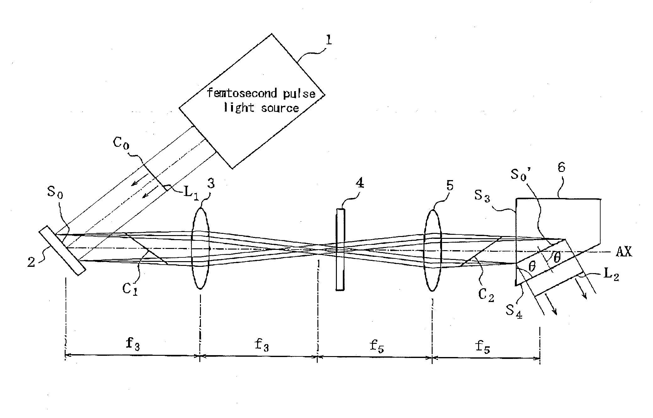
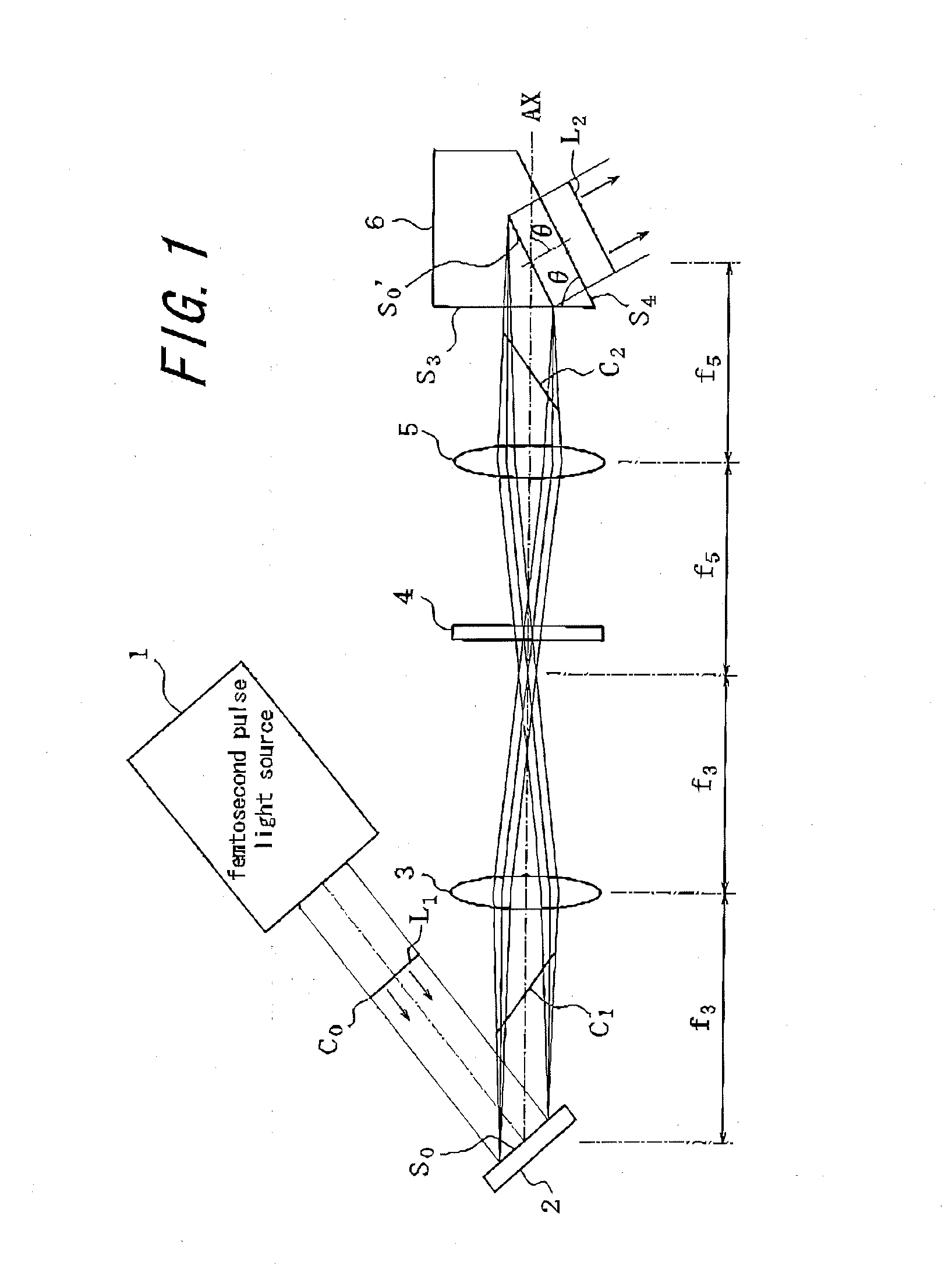
[0023]FIG. 1 is a diagram illustrating a schematic configuration of a terahertz wave generator according to a first embodiment of the present invention. The terahertz wave generator includes a femtosecond pulse light source 1 serving as a source of an electromagnetic wave, a diffraction grating 2 serving as a diffraction element, a lens 3, a one-half wavelength plate 4, a lens 5, and a LiNbO3 crystal 6 serving as a nonlinear optical crystal. The lens 3, the one-half wavelength plate 4 and the lens 5 constitute an optical system for transmitting electromagnetic waves that have been diffracted by the diffraction grating.

[0024]The femtosecond pulse light source 1 is a light source for generating a near-infrared light L1 in a pulse form, and employs, for example, a titanium-sapphire laser capable of generating broadband infrared pulses with a wavelength range of 750 to 850 nm.

[0025]The diffraction grating 2 is disposed on an optical path on which the near-infrared light L1 outputted fro...

second embodiment

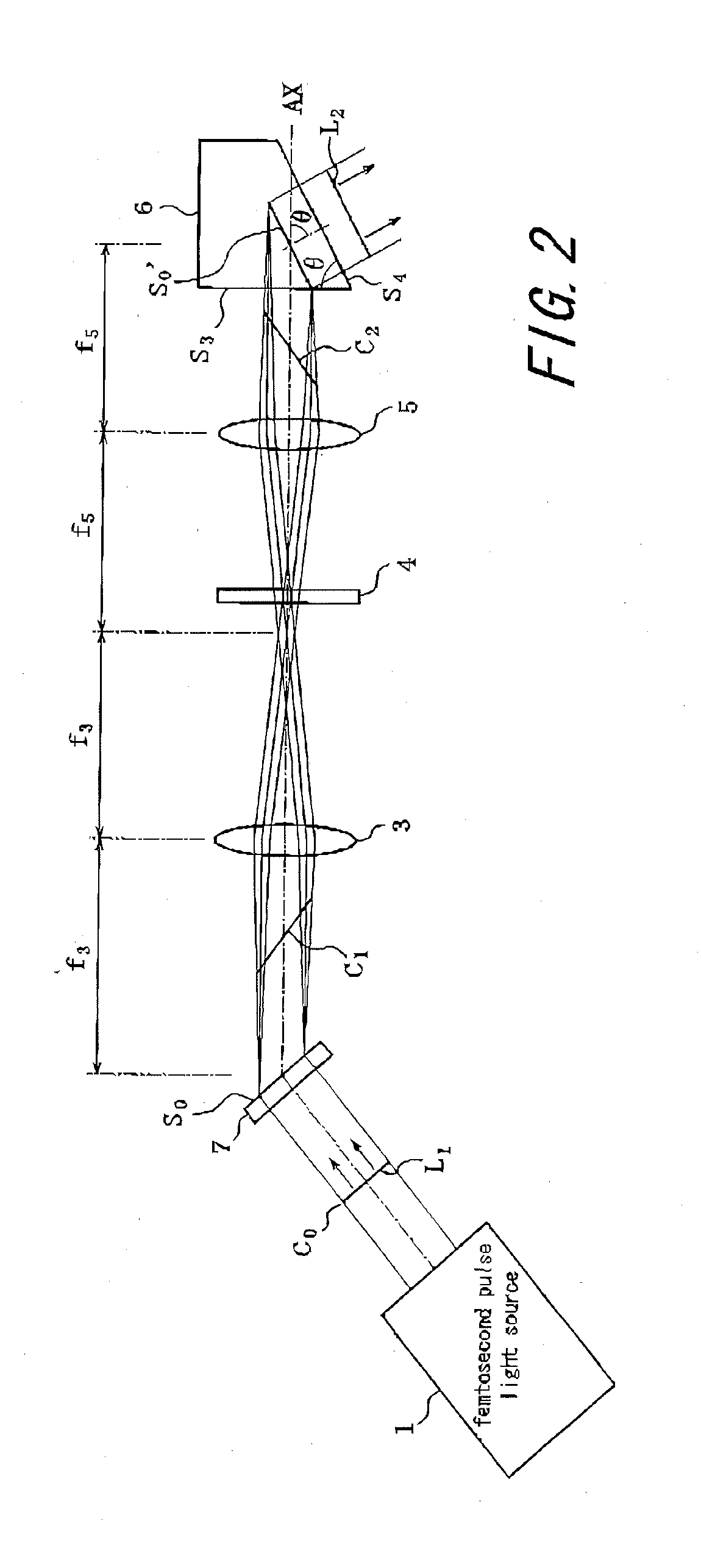
[0036]FIG. 2 is a diagram illustrating the schematic configuration of a terahertz wave generator according to a second embodiment of the present invention. In this embodiment, the reflection-type diffraction grating 2 employed in the terahertz wave generator according to the first embodiment is replaced with a transmission-type diffraction grating 7. With this replacement, the femtosecond pulse light generator 1 is disposed such that the diffraction grating 7 is irradiated with the near-infrared light L1 from the back side of the diffraction grating 7. The other configurations are the same as those in the first embodiment. Therefore, the same reference characters are attached to the same constituent elements, and explanation thereof will be omitted.

[0037]With this configuration, the near-infrared light L1 entering the diffraction grating 7 is not blocked by the lens 3 even when the lens 3 having short focal length f3 is selected. Therefore, in addition to the effect obtained by the ...

third embodiment

[0038]FIG. 3 is a diagram for explaining a configuration and operation of a nonlinear optical crystal used in a terahertz wave generator according to a third embodiment of the present invention. In the third embodiment, the LiNbO3 crystal 6 in the first embodiment is replaced with LiNbO3 crystals 61, 62, which will be described below. The other configurations are the same as those in the first embodiment.

[0039]In FIG. 3, the nonlinear optical crystal is formed by two LiNbO3 crystals 61, 62, The LiNbO3 crystal 62 has a plane S5 perpendicular to an optical axis AX of the near-infrared light L1, and a plane S1 oriented at an angle θ with respect to the plane S5, Further, the LiNbO3 crystal 62 is jointed with the LiNbO3 crystal 61 having a plane 52 parallel to the plane S1. Similar to the case in the first embodiment, the angle θ is a tilting angle of the pulse front of the near-infrared light L1 for satisfying above-described Expression (2), which is a phase matching condition. The LiN...


PUM

PropertyMeasurementUnit
wavelengthaaaaaaaaaa
phaseaaaaaaaaaa
poweraaaaaaaaaa

Abstract

A terahertz wave generator includes a femtosecond pulse light source 1 that outputs a near-infrared light L1, which is a pulse light, a diffraction grating 2 that diffracts the outputted near-infrared light L1, an optical system including a lens 3 and a lens 5, and a LiNbO3 crystal 6 for generating terahertz waves L2 with irradiation of the near-infrared light L1. The optical system including the lens 3 and the lens 5 is arranged such that at least a pan of a plane S0′ optically conjugated to a diffractive plane S0 of the diffraction grating 2 is formed within the LiNbO3 crystal 6, and a direction normal to the conjugated plane and a direction normal to a plane formed by the pulse front of the non-linear L1 are matched with each other within the LiNbO3 crystal 6. This makes it possible for the near-infrared light L1 to cause the nonlinear optical effect to efficiently occur in the wide range, whereby high-efficient and high-power terahertz waves can be obtained.

Description

TECHNICAL FIELD[0001]The present invention relates to a terahertz wave generator that generates high-power terahertz waves.BACKGROUND ART[0002]Conventionally, in a field of sensing and imaging of transparent substance (for example, water), there have been known techniques that employ terahertz waves.[0003]Recently, in particular, the terahertz wave technology has been rapidly developing with the establishment of methods of generating and detecting the terahertz waves. However, the conventional terahertz wave generators cannot sufficiently increase efficiency in generating terahertz waves, and its output power is insufficient for use in the large-diameter terahertz wave imaging, or in the field of application using the large-diameter terahertz wave imaging such as sensing.[0004]Further, recently, there is proposed a method of generating high-output terahertz waves utilizing difference frequency mixing, which is one type of nonlinear optical effects (see, for example, “Efficient terah...

Claims


Application Information

Patent Timeline
Patent Type & Authority Applications(United States)
IPC IPC(8): G02F1/37G02F1/355
CPCG02F1/3534G02F2203/13G02F1/3544
Inventor DOI, ATSUSHINAMIKI, MITSURU
Owner OLYMPUS CORP
Why Eureka
Try Eureka