Method for Load Regulation of an Ammonia Plant

a technology of ammonia plant and load regulation, which is applied in the direction of energy input, chemical/physical/physicochemical process, bulk chemical production, etc., can solve the problems of reactor vessel fatigue stress, reactor vessel overheating, and ammonia synthesis reactor cannot operate at the nominal elevated pressure (100-500 bar), so as to protect the reactor from overheating and improve the efficiency. , the effect of reducing the cost of energy

Active Publication Date: 2013-05-02
CASALE SA
View PDF2 Cites 9 Cited by
  • Summary
  • Abstract
  • Description
  • Claims
  • Application Information

AI Technical Summary

Benefits of technology

[0025]The main advantage of the invention is that the ammonia plant can be operated at a partial load keeping a good efficiency and protecting the reactor from overheating. The ammonia plant can follow a time-varying availability and / or price of a source feed such as electric energy and / or water in embodiments with electrolysis-based front end. This is possible even on a short-term basis, such as daily or hourly.
[0026]Referring more in detail to embodiments where the hydrogen feed comes from electrolysis of water, the ammonia plant can be operated at full nominal load (100%) when the full electric power is available and / or the energy is cheaper, and can be operated at a reduced load less than 50% when less power is available and / or price is higher. The same is applicable to availability or cost of water. This means that the electrolysis-based ammonia production becomes more attractive from an economical point of view.
[0027]Hence, electrolysis-based ammonia plant can be efficiently powered by renewable energy sources such as solar or wind. The load of the ammonia plant can be regulated in a flexible manner, for adaptation to the fluctuations of the power output provided by renewable energy sources. Hence, for example, an ammonia plant can be partly or fully powered by a solar or wind power plant, leading to a virtually carbon-free ammonia production. This option is attractive especially for small-scale ammonia production in a remote site or for agricultural use, where ammonia can be produced on-site without the need of a hydrocarbon feed.
[0028]A small-scale ammonia plant is understood as a plant with a nominal capacity of less than 50 tons per day of ammonia.
[0029]The invention can also be used to regulate the load of the ammonia plant following the price of energy, either produced with a conventional or renewable source. For example when price of energy is higher it could be preferred to turn down the ammonia plant, or to sell directly the energy whenever applicable; when the price is lower it could be preferred to use the energy for powering the electrolysis unit and hence to produce ammonia.
[0030]It has been found that by raising the concentration of inert in the loop the efficiency at partial loads remains surprisingly good. For example an ammonia plant operated at a 10% load, according to the invention, has a specific consumption of electric energy (kWh per kg of ammonia output) which is only 10-15% higher than specific consumption at nominal capacity. For a comparison, specific consumption of a conventional large ammonia plant is almost doubled when passing from nominal capacity to 50% partial load.

Problems solved by technology

The ammonia synthesis reactor, however, cannot operate at the nominal elevated pressure (100-500 bar) when make-up gas feed falls below a minimum flow rate.
Catalyst would be in excess over the make-up gas, and the temperature of the reaction would increase in a dangerous manner.
But this would introduce another drawback, because the reactor vessel would suffer fatigue stress due to frequent pressurization and depressurization.
Another problem is that the operation of the synthesis loop at a partial load is much less efficient compared to operation at full capacity and, as a consequence, the specific consumption is much higher.
These drawback are of a minor importance in large ammonia plants, which are in any case unable to operate below a 50%-60% of nominal capacity, due to minimum turn down of the front end and because there would be no incentive to run such a large plant at a low partial load.
The same drawbacks however are an obstacle to the implementation of small-scale ammonia production based on electrolysis of water instead of steam reforming, where it could be necessary or desirable to turn down the ammonia production to a low partial load, well below 50%.
As stated above, regulation of the synthesis pressure is not a satisfactory solution for the risk of a fatigue failure of the reactor; another solution could be given by providing several ammonia production lines in parallel, each line having its own make-up gas compressor and high-pressure loop, but this would increase the capital cost and is generally not acceptable.
Hence the prior art does not provide a solution to the above problem.
In such a case the same problems above (risk of reactor overheating, low efficiency, fatigue stress if pressure is reduced) are encountered.

Method used


Image

  • Method for Load Regulation of an Ammonia Plant
  • Method for Load Regulation of an Ammonia Plant

Examples


example

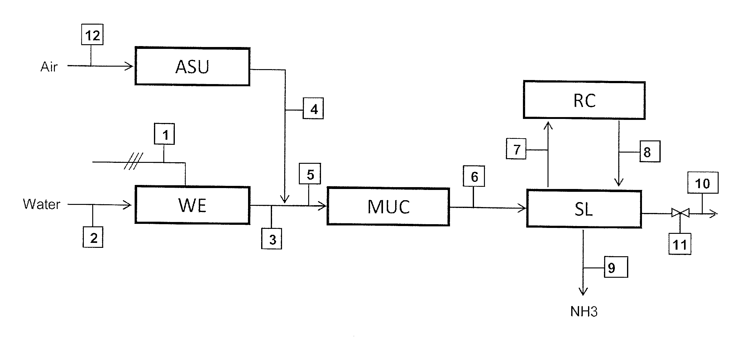
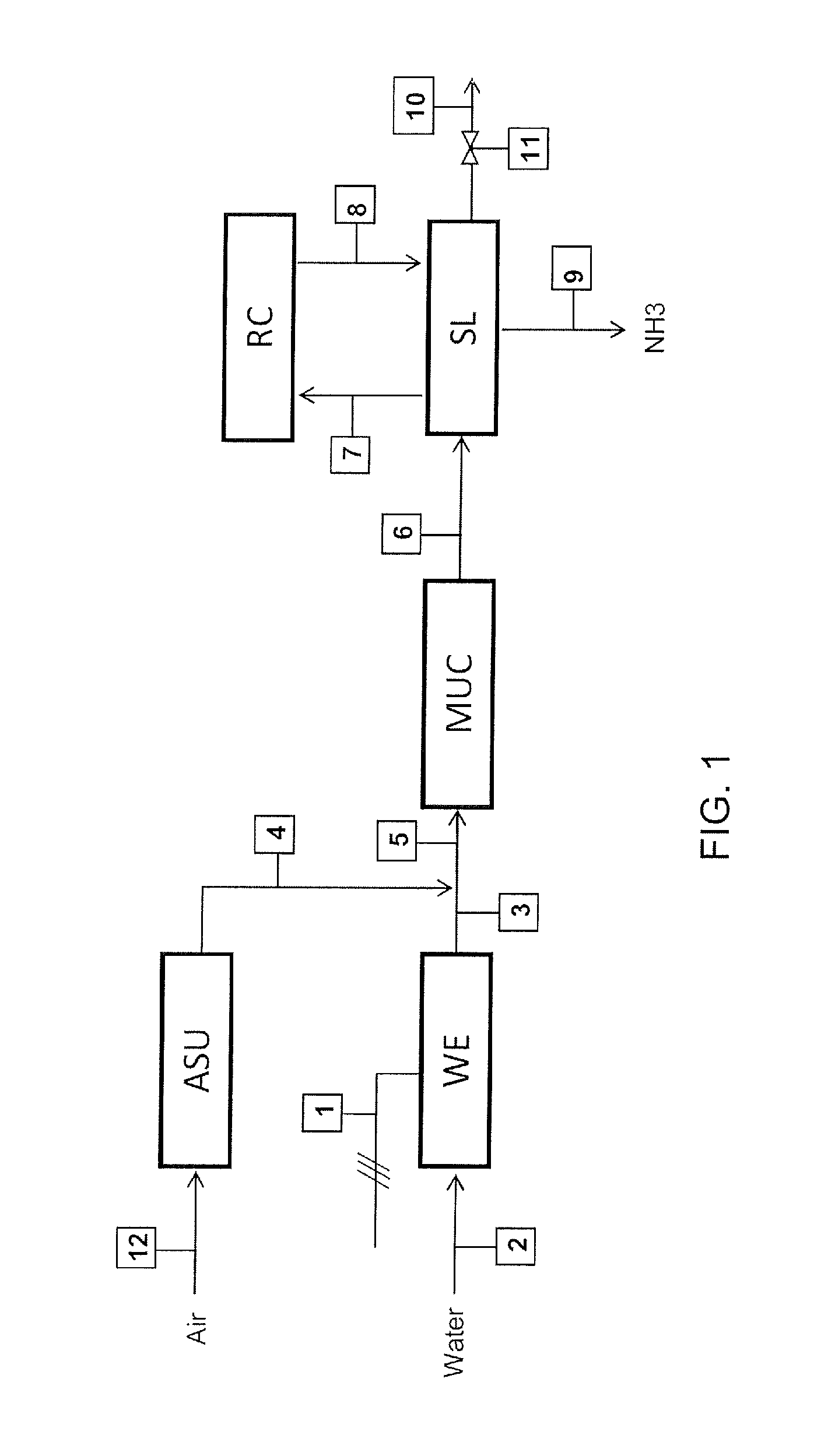
[0046]The example refers to a small ammonia according to FIG. 1 plant rated at 120 kg / h of ammonia. The following table 1 show the composition of the streams in FIG. 1 when the plant operates at nominal (7 kmol / h equal to 120 kg / h of ammonia) output. The power input, in this case, is 1300 kW which means that specific energy consumption is 1300 / 120=10.8 kWh per kg of ammonia.

TABLE 1Stream No.3678910Molar Flow11156565 70.3(kmol / h)mol % H210074.56060—60mol % N2—252020—20mol % NH3——101010010mol % Ar—0.51010—10

[0047]The following table 2 refers to the same plant operated at a 10% load, which means 0.7 kmol / h or 12 kg / h of ammonia.

TABLE 2Stream No.3678910Molar Flow11.525250.70.01(kmol / h)mol % H210074.53030—30mol % N2—251010—10mol % NH3——101010010mol % Ar—0.55050—50

[0048]The hydrogen feed 3 and, hence, the make-up gas feed 6 are ten times smaller compared to table 1. To compensate for this lower feed, the molar flow rate of the purge gas (stream 10) is reduced by a factor greater than ten,...


PUM

PropertyMeasurementUnit
pressureaaaaaaaaaa
temperatureaaaaaaaaaa
pressureaaaaaaaaaa

Abstract

A method for regulation of an ammonia plant where a purge gas (10) containing inerts is extracted from ammonia synthesis loop (SL), and where the ammonia plant is operated at a partial load by keeping the ammonia synthesis loop at a nominal high pressure, and reducing the purge rate in order to increase concentration of inerts in the ammonia synthesis loop and avoid overheating of the ammonia reactor; preferably a water electrolysis section (WE) produces a hydrogen feed (3) and an air separator produces a nitrogen feed (4); hydrogen and nitrogen are mixed to form a make up gas (5) which is reacted at a high-pressure in said ammonia synthesis loop (SL).

Description

CROSS-REFERENCE TO RELATED APPLICATIONS[0001]This application claims priority to European Patent Application No. 11187431.9, filed Nov. 2, 2011, the entire content of which is incorporated herein by reference.FIELD OF THE INVENTION[0002]The present invention relates to production of ammonia. The invention relates to a method for regulation of an ammonia plant. The invention also relates to a process and plant which implement the method for a flexible production of ammonia.PRIOR ART[0003]Synthesis of ammonia starting from hydrogen and nitrogen is known. According to the known art, a make-up gas comprising hydrogen and nitrogen is catalytically converted to ammonia in a high-pressure (HP) synthesis loop, usually at a pressure around 80-300 bar. This make-up syngas is produced in a front-end section, where hydrogen is produced by steam reforming of a hydrocarbon source. The hydrocarbon source is natural gas or a synthesis gas produced by partial oxidation of another carbon source, e.g....

Claims


Application Information

Patent Timeline
Patent Type & Authority Applications(United States)
IPC IPC(8): C01C1/04B01J19/00
CPCC01B3/025C01C1/0476C01C1/0482C01B2203/068Y02E60/366C01B2203/02C01B2203/1685Y02P20/133Y02P20/52Y02E60/36
Inventor OSTUNI, RAFFAELEZARDI, FEDERICO
Owner CASALE SA
Why Eureka
Try Eureka