Supercharge Your Innovation With Domain-Expert AI Agents!

Metal foil laminate, substrate for mounting led, and light source device

a technology of metal foil and substrate, applied in the field of metal foil laminate, can solve the problems of deterioration of reflection efficiency, rigid and brittle nature, difficult to deal with ceramic substrates, etc., and achieve the effect of reducing thickness, reducing reflectance, and effectively preventing peeling of metal foil (a)

Active Publication Date: 2013-05-09
MITSUBISHI CHEM CORP
View PDF4 Cites 1 Cited by
  • Summary
  • Abstract
  • Description
  • Claims
  • Application Information

AI Technical Summary

Benefits of technology

The present invention relates to a metal foil laminate that can withstand size increments and thickness reduction. The laminate includes a resin layer containing polyorganosiloxane and an inorganic filler, and a metal foil. The laminate has a peel strength of 0.95 kN / m or greater, which prevents peeling of the metal foil during various processes. Additionally, the laminate has a high reflectance in the visible light region and low decreased reflectance after heat treatment, which makes it suitable for use as a printed wiring substrate for packaging LEDs or other light emitting devices.

Problems solved by technology

In printed wiring substrates formed from thermosetting resin compositions that have been conventionally used, there may be observed a tendency that the degree of whiteness decreases, causing yellowing, and the reflection efficiency is deteriorated, in such an environment under thermal load.
On the other hand, ceramic substrates are excellent in terms of heat resistance, but have a rigid and brittle nature.
Therefore, there are limitations in attempting to promote size increment and thickness reduction as in the case of resin substrates, and there is a possibility that it may be difficult to deal with ceramic substrates as substrates for general applications for illumination or display applications in the future.

Method used


Image

  • Metal foil laminate, substrate for mounting led, and light source device
  • Metal foil laminate, substrate for mounting led, and light source device
  • Metal foil laminate, substrate for mounting led, and light source device

Examples


example 1

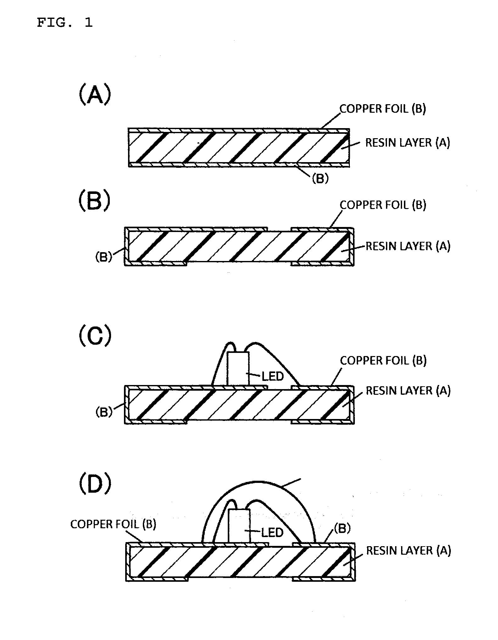
[0118]60 parts by mass of a vinyl group-containing polysiloxane resin (“TSE2913U” manufactured by Momentive Performance Materials, Inc., containing 10% to 20% of silica) that was crosslinkable by γ-radiation, and 40 parts by mass of titanium oxide (particle size: 0.3 μm, rutile type, surface-treated with a siloxane compound) were mixed in a planetary mixer, and thus a resin composition (content of crosslinking agent: 0% by mass) was obtained. The resin composition thus obtained was extruded into a resin sheet form having a thickness of 100 μm on a PET film by using an extruder, and also a copper foil (surface-treated with a silane coupling agent) having a thickness of 18 μm was laminated on the resin sheet. Thus, a one-sided copper-clad laminate was obtained.

[0119]Subsequently, the PET film of the one-sided copper-clad laminate thus obtained was peeled off, and a copper foil (surface-treated with a silane coupling agent) having a thickness of 18 μm was laminated thereon. Thereafter,...

example 2

[0120]A both-sided copper-clad film (metal foil laminate (sample)) was produced in the same manner as in Example 1, except that a vinyl group-containing polysiloxane resin (“TSE2571-5U” manufactured by Momentive Performance Materials, Inc., containing 20% to 30% of silica) that was crosslinkable by γ-radiation was used.

example 3

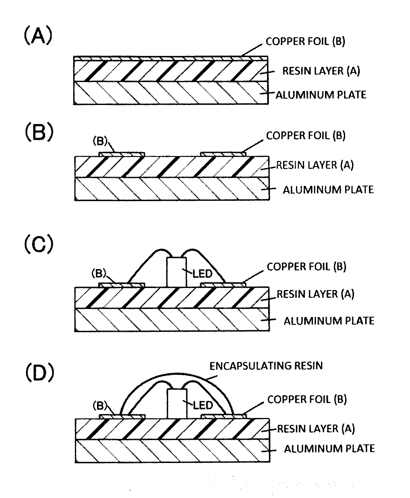
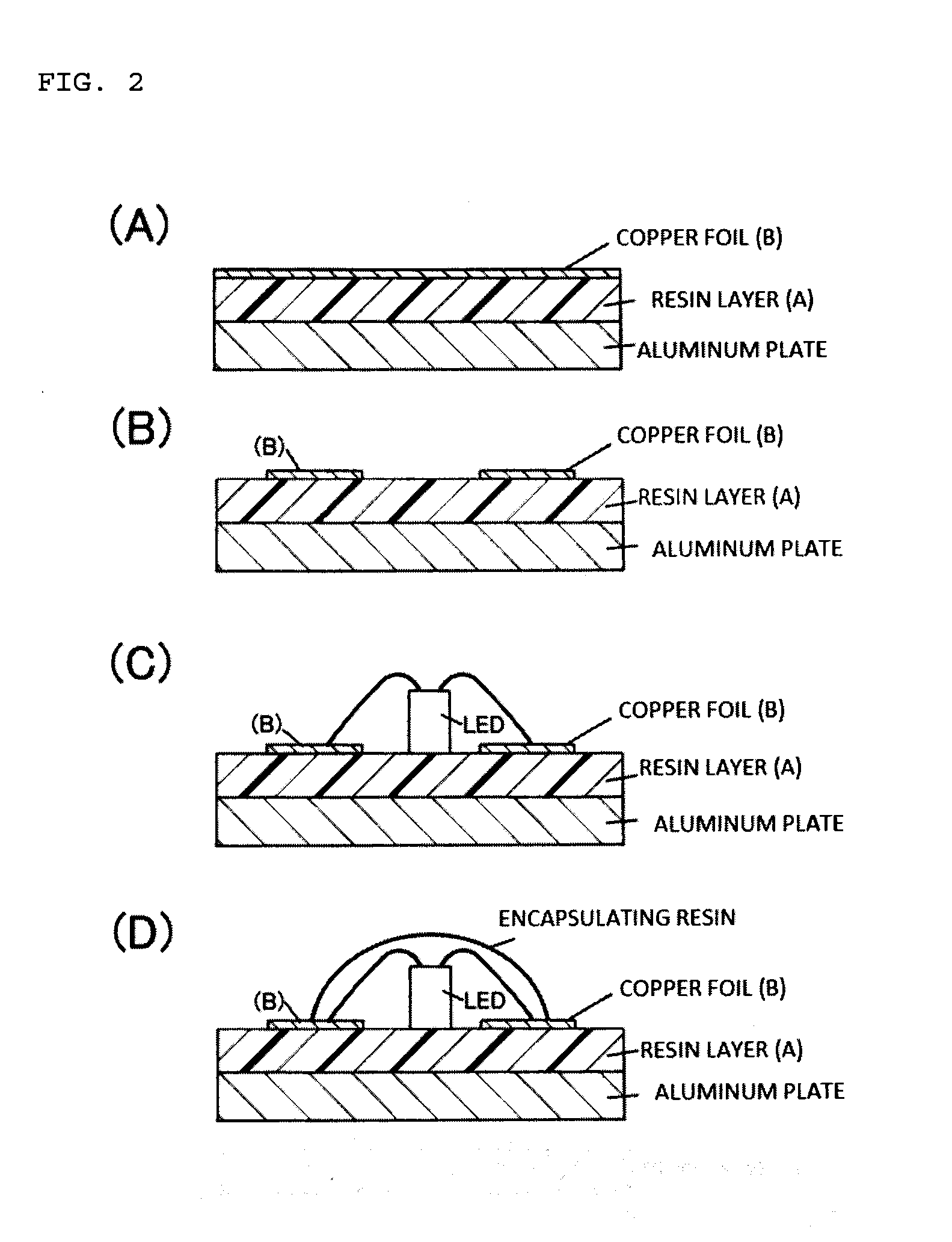
[0121]A one-sided copper-clad film was produced by using the materials of Example 1, and the one-sided copper-clad film was laminated on an aluminum plate on which an adhesive primer (“XP81-A6361A,B” manufactured by Momentive Performance Materials, Inc.) had been applied in advance. Subsequently, the polysiloxane resin was cured by γ-radiation at an exposure dose of 50 kGy, and thus an aluminum substrate (metal foil laminate (sample)) was produced.


PUM

PropertyMeasurementUnit
Temperatureaaaaaaaaaa
Fractionaaaaaaaaaa
Fractionaaaaaaaaaa

Abstract

Provided is a metal foil laminate that: has heat resistance; has high reflectance in the visible light range; has little decrease in reflectance in environments with a high-temperature thermal load; is compatible with large surface areas; and can be used for printed circuit boards for mounting LEDs that have excellent adhesion with metals. The metal foil laminate is characterized in that: a laminate has metal foil on at least one side of a resin layer (A) containing a polyorganosiloxane and an inorganic filler; the 90° peel strength between said resin layer (A) and said metal foil is at least 0.95 kN / m, and the mean reflectance at wavelengths of 400 to 800 nm on the surface that is exposed when the resin layer (A) is exposed by peeling and removing said metal foil is at least 80%; and the decrease in the reflectance at a wavelength of 470 nm after being treated with heat for 10 minutes at 260° C. is not more than 5%.

Description

TECHNICAL FIELD[0001]The present invention relates to a metal foil laminate having excellent heat resistance and high reflectance characteristics. The present invention relates to a metal foil laminate that can be suitably utilized as, for example, a substrate for mounting LED or the like, and a substrate for mounting LED and a light source device that use this metal foil laminate.BACKGROUND ART[0002]Chip type LEDs in which elements are directly packaged on a pattern of a printed wiring substrate and are encapsulated with resins, are advantageous for miniaturization and thickness reduction, and therefore, such chip type LEDs are widely used in electronic instruments such as number pad illumination of mobile telephones, and backlights for small-sized liquid crystal displays.[0003]In recent years, the technologies for increasing the luminance of LEDs are in marked progress, and the luminance of LEDs is ever increasing. Along with this progress, the amount of heat emission of the LED e...

Claims


Application Information

Patent Timeline
IPC IPC(8): B32B15/08B32B5/00H01L33/60
CPCG02B5/0808Y10T428/266H05K1/0373H05K3/389H05K2201/0162H05K2201/0209H01L2224/48227B32B5/00B32B15/08H01L33/60G02B5/085H01L33/64H05K3/0061H05K3/022H01L33/62H01L2924/12044Y10T428/31663Y10T428/31678H01L2924/00
Inventor MATSUI, JUNTERAI, TOMOHIKOSUZUKI, SYUUJI
Owner MITSUBISHI CHEM CORP
Features
  • R&D
  • Intellectual Property
  • Life Sciences
  • Materials
  • Tech Scout
  • Unparalleled Data Quality
  • Higher Quality Content
  • 60% Fewer Hallucinations
Learn More