Glass plate
a technology of glass plate and glass plate, which is applied in the field of glass plate, can solve the problems of deterioration of display brightness, parallax barrier system, and essentially the requirement of glasses at the time of watching a television, and achieve the effects of improving denitrification resistance, reducing liquidus temperature, and reducing the number of glasses
- Summary
- Abstract
- Description
- Claims
- Application Information
AI Technical Summary
Benefits of technology
Problems solved by technology
Method used
Image
Examples
example 1
[0072]Hereinafter, examples of the present invention are described.
[0073]Table 1 shows examples of the present invention (Sample Nos. 1 to 11).
TABLE 1No. 1No. 2No. 3No. 4No. 5No. 6No. 7No. 8No. 9No. 10No. 11GlassSiO258.754.752.754.750.752.748.755.753.750.756.9composi-Al2O319.019.021.023.023.025.025.020.020.020.013.0tionB2O3——————————2.0(wt %)Na2O8.010.010.08.010.010.08.015.015.015.015.0K2O5.07.07.07.05.05.07.05.05.05.05.0MgO2.54.52.52.54.52.54.54.04.04.02.0CaO6.54.56.54.56.54.56.5———2.0ZrO2——————————4.0P2O5————————2.05.0—SnO20.30.30.30.30.30.30.30.30.30.30.1Density (g / cm3)2.502.522.532.502.552.512.562.482.482.472.52Ps (° C.)625593601639618638635582577588523Ta (° C.)673639647690663688681631626639563Ts (° C.)898853858930866921889864860901762104 dPa · s (° C.)1,2521,1911,1931,2931,1811,2711,2021,2271,2251,2191,100103 dPa · s (° C.)1,4381,3691,3701,4751,3441,4461,3621,4161,4111,4021,280102.5 dPa · s1,5541,4811,4801,5861,4471,5561,4611,5341,5271,5141,396(° C.)Thermal829395858986851031031...
example 2
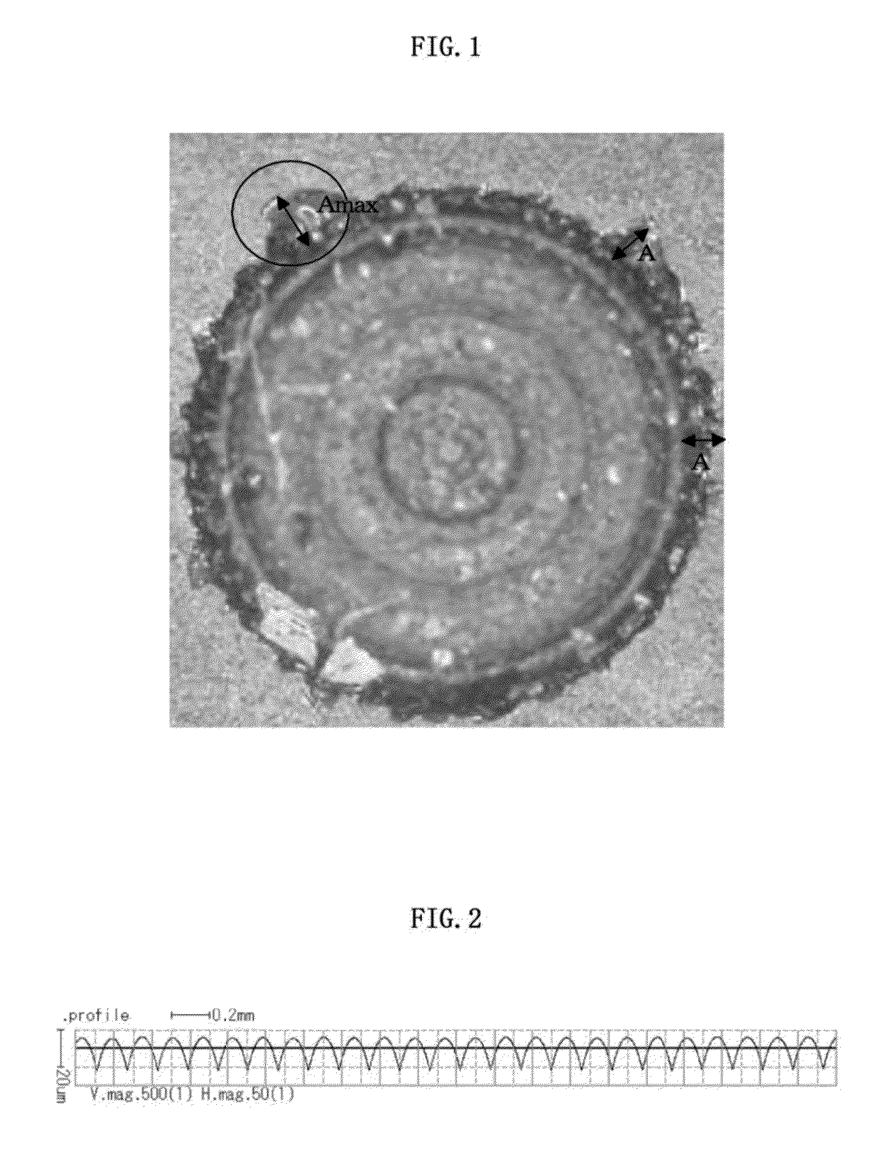
[0086]Glass raw materials were blended so that the glass composition of Sample No. 10 of Example 1 was attained, yielding a glass batch. After that, the glass batch was melted in a melting apparatus, and then the resulting molten glass was formed into a glass sheet having a thickness of 1 mm by an overflow down-draw method. Subsequently, the resulting glass sheet was subjected to convex / concave forming processing in one surface. The convex / concave forming processing was carried out according to the procedure of rough polishing, polishing, and fine polishing in a polishing line in which a grinding roller having the reverse shape of a convex / concave shape to be formed in the surface of the glass sheet is arranged. Finally, the surface shape of the convex / concave portion (lens portion) was measured with a surfcorder. Specifically, the surface shape was measured in a direction orthogonal to the direction in which the convex / concave portion (lens portion) was formed under the following c...
example 3
[0088]The glass sheet having the convex / concave portion (lens portion) described in Example 2 was subjected to ion exchange treatment under the same condition as in Example 1. Next, a surface of the glass sheet in which no convex / concave portion (lens portion) had been formed was used to measure a surface stress. As a result, it was confirmed that the glass sheet had a compression stress layer having a compression stress value of 995 MPa and a depth of 81 μm.
PUM
| Property | Measurement | Unit |
|---|---|---|
| size | aaaaa | aaaaa |
| diameter | aaaaa | aaaaa |
| diameter | aaaaa | aaaaa |
Abstract
Description
Claims
Application Information
 - R&D
- Intellectual Property
- Life Sciences
- Materials
- Tech Scout
- Unparalleled Data Quality
- Higher Quality Content
- 60% Fewer Hallucinations
Browse by: Latest US Patents, China's latest patents, Technical Efficacy Thesaurus, Application Domain, Technology Topic, Popular Technical Reports.
© 2025 PatSnap. All rights reserved.Legal|Privacy policy|Modern Slavery Act Transparency Statement|Sitemap|About US| Contact US: help@patsnap.com

