Supercharge Your Innovation With Domain-Expert AI Agents!

Method of manufacturing micro chamber plate with built-in sample and analytic micro chamber plate, analytic micro chamber plate and apparatus set for manufacturing analytic micro chamber plate with built-in sample

a technology of micro chamber plate and built-in sample, which is applied in the field of micro chamber plate, can solve the problems of not being able to analyze a large number of genes compared to a large amount of used sample, waste of time, and inability to analyze a large number of genes, so as to reduce the size of the analytic micro chamber plate, prevent the measurement error of the optical measuring part, and simple structure

Active Publication Date: 2013-05-09
BIONEER
View PDF1 Cites 6 Cited by
  • Summary
  • Abstract
  • Description
  • Claims
  • Application Information

AI Technical Summary

Benefits of technology

The present invention provides a device for analyzing samples, such as nucleic acid, using optical measurements. The device has a simple structure and is easy to control, reducing analysis time. The device includes a separation membrane that prevents contamination and allows for complete injection of the sample solution without any remaining gas. The separation membrane is sealed with polymer oil to prevent cross-contamination. The device can be used with multiple samples simultaneously, reducing analysis time. The manufacturing process and cost of the device is reduced because the separation membrane and optical measuring part are integrally formed with the analytic micro-chamber plate.

Problems solved by technology

In the conventional real-time PCR apparatus manufactured by Roche, in which a reaction sample of 10-500 is used, however, there is a problem that it is not possible to analyze a large number of genes compared to a large amount of used sample.
In the above-mentioned method, however, since different solutions have to be applied to each micro-chamber using a pipette, much time is spent on that.
Herein, in order to apply the different solutions, it takes lots of time due to a cleaning process which has to be performed before applying each of the different solutions.
Thus, there is a problem in that it is difficult to use the 384 plates or more.
However, since cross contamination of the PCR solution is occurred when covering or separating the cover glass, it is inconvenient that the cover glass has to be removed while a water-repellent film is interposed between the cover glass and the wafer, the water-repellent film has to be removed after drying the PCR solution and then an analysis process has to be performed.
Further, there is a problem in that it cannot be used in qPCR technology.
However, in this method, there are some problems that a separate nano jet pipetting system for micro-array is needed to inject the solution, it takes lots of time to perform the pipetting operation and there is also a high risk of the cross contamination among the reaction solutions due to flowing of the mineral oil when the plate is moved.
Thus since excitation light and luminescence is scattered and dispersed upon the optical measurement, the measurement error is increased.
However, since a carrier in which primers / probes are immobilized is needed, it cannot be applied to a real-time quantitative PCR method in which uniform optical characteristics are required.
If the injection hole is not completely sealed, there is a problem that the reaction solution is evaporated upon the PCR.
Further, since the film reactor has a complicated structure in order to treat a few thousands of samples, it is substantially impossible to manufacture it.
In case of a plate for analyzing a great number of samples, since a few thousands of different solutions are injected at the micro-chambers, a special pipetting system such as a nano-liter pipetting system is needed, much time is spent on that and also erroneous injections may be occurred.
Further, since the micro-chamber cannot be completely filled with the solution, bubbles are generated, and the water vapors are formed at an upper portion of the micro-chamber when raising the temperature, and thus the optical measurement is disturbed by the scattering.
However, in the seventh method, since the injection part and the optical measuring part are formed separately, it has a complicated structure.
And the oil layer formed on the injection part becomes transparent, and thus a deviation problem in the measurement results may be occurred according to a stained state of a bottom surface.
However, since the eighth method has a structure that a sample to be injected is directly applied to a porous membrane, it has some problems as follows: 1) in case that the injection of the sample is achieved by a vacuum, centrifugal force is applied in order to prevent running-out of the sample while the vacuum is applied.
Herein, discharging of gas through pores of the porous membrane is disturbed by the centrifugal force and surface tension of the sample; 2) since the gas in the micro-chamber is compressed by the centrifugal force and thus a volume thereof is contracted, the gas does not obtain enough buoyancy to get out of the micro-chamber through the membrane, but is remained in the form of small bubbles and then expanded again in the measurement condition of atmospheric pressure, thereby disturbing the measurement.

Method used


Image

  • Method of manufacturing micro chamber plate with built-in sample and analytic micro chamber plate, analytic micro chamber plate and apparatus set for manufacturing analytic micro chamber plate with built-in sample
  • Method of manufacturing micro chamber plate with built-in sample and analytic micro chamber plate, analytic micro chamber plate and apparatus set for manufacturing analytic micro chamber plate with built-in sample
  • Method of manufacturing micro chamber plate with built-in sample and analytic micro chamber plate, analytic micro chamber plate and apparatus set for manufacturing analytic micro chamber plate with built-in sample

Examples


first embodiment

[0071]The first embodiment relates to a method of manufacturing an analytic micro-chamber plate according to the present invention.

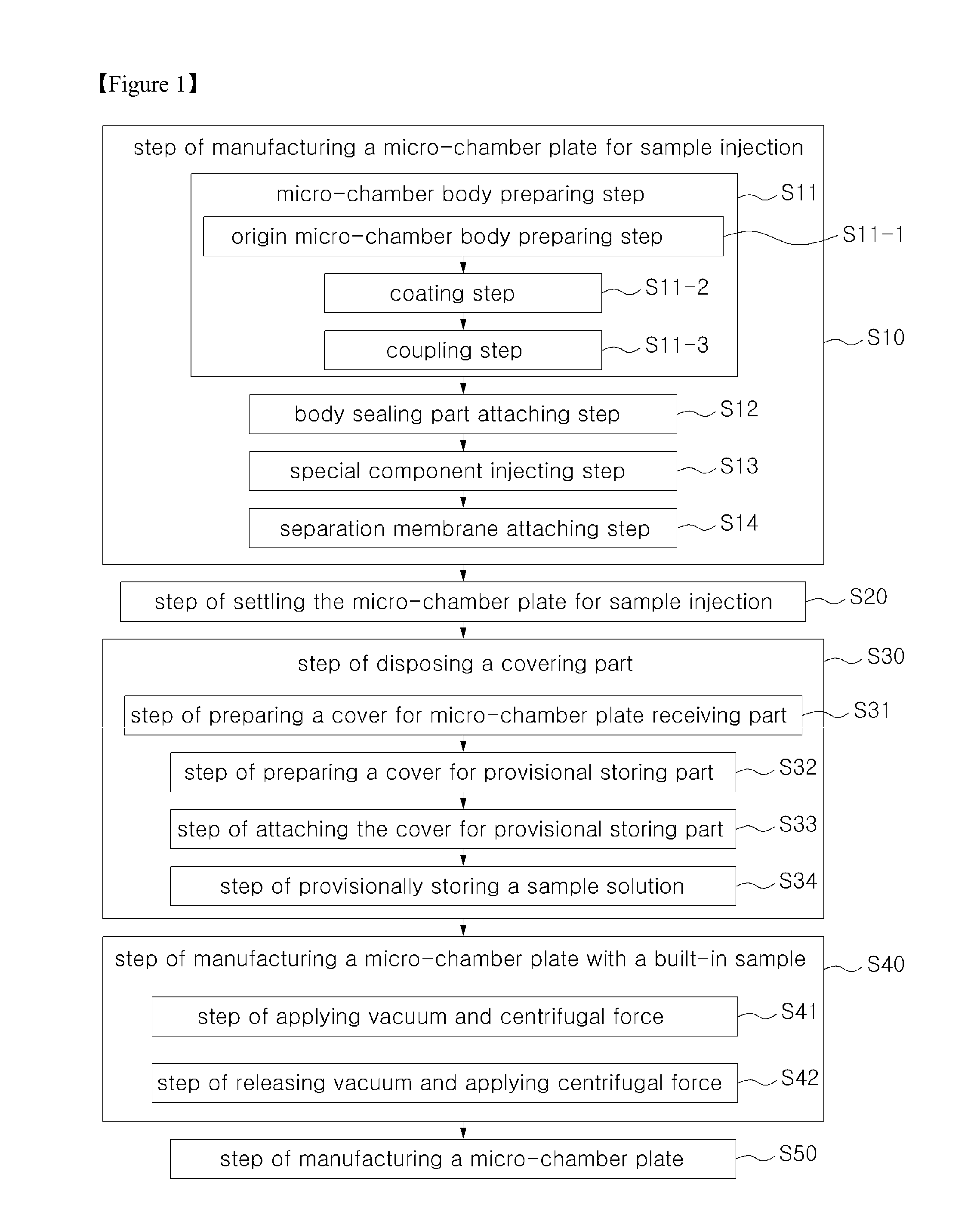
[0072]Referring to FIG. 1, the first embodiment includes a step S10 of manufacturing a micro-chamber plate for sample injection, a step S20 of settling the micro-chamber plate for sample injection, a step S30 of disposing a covering part, a step S40 of manufacturing a micro-chamber plate with a built-in sample, and a step S50 of manufacturing an analytic micro-chamber plate.

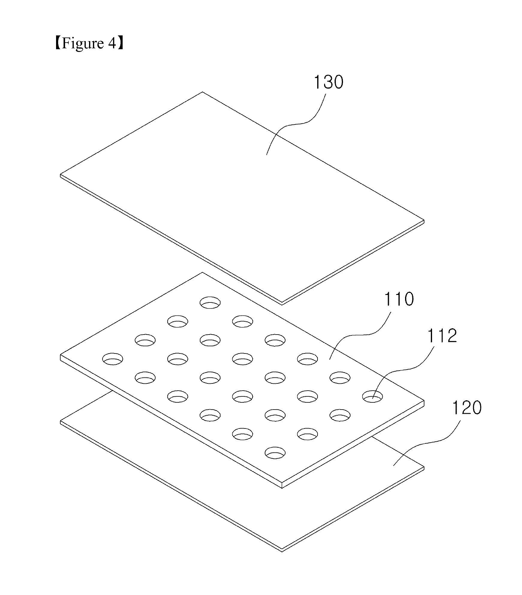
1. Step S10 of Manufacturing the Micro-Chamber Plate for Sample Injection Referring to FIGS. 2 to 4, in the step S10 of manufacturing the micro-chamber plate for sample injection, the micro-chamber plate 100 for sample injection, in which a special component 140 is built in, is manufactured. The micro-chamber plate 100 for sample injection includes a micro-chamber body 110, a body sealing part 120 and a separation membrane 130.

[0073]Therefore, referring to FIGS. 1 to 4, the step S10 o...

second embodiment

[0115]The second embodiment relates to a method of manufacturing the micro-chamber plate with a built-in sample according to the present invention.

[0116]The second embodiment includes a step S10 of manufacturing a micro-chamber plate for sample injection, a step S20 of settling a micro-chamber plate for sample injection, a step S30 of disposing a covering part, and a step S40 of manufacturing a micro-chamber plate with the built-in sample which are described in the first embodiment. The description thereof is based on that of the first embodiment.

third embodiment

[0117]The third embodiment relates to an analytic micro-chamber plate.

[0118]The analytic micro-chamber plate (not shown) is the same as the micro-chamber plate 100A with the built-in sample (referring to FIG. 17) except the separation membrane 130, and thus it will be described with reference with FIG. 17.

[0119]Referring to FIGS. 6 and 17, the third embodiment includes an origin micro-chamber body 110-1 in which the unit number of chamber holes 110-1H are formed to pass through upper and lower surfaces thereof.

[0120]Referring to FIGS. 7 and 17, a polymer coating layer 110-2 is formed on a surface of the origin micro-chamber body 110-1 and inner surfaces of the unit number of origin chamber holes 110-1H (referring to FIG. 6). The unit number of chamber holes 112 corresponding to the unit number of origin chamber holes 110-1H are formed by the polymer coating layer 110-2.

[0121]Referring to FIGS. 8 and 17, a body sealing part 120 is formed at a lower surface of the micro-chamber body 1...


PUM

PropertyMeasurementUnit
depthaaaaaaaaaa
widthaaaaaaaaaa
thicknessaaaaaaaaaa

Abstract

The present invention relates to a micro chamber plate, and more particularly, to an analytic micro chamber plate in which a plurality of reaction solutions including a primer or probe selectively reacting with a nucleic acid react with each other without cross-contamination to measure and analyze a fluorescence level in real-time so as to analyze biological sample solution including a large amount of nucleic acids. Also, the present invention relates to a method of manufacturing the analytic chamber plate. Also, the present invention relates to a method of manufacturing a micro chamber plate with a built-in sample used for manufacturing the analytic chamber plate. Also, the present invention relates to an apparatus set for manufacturing the micro chamber plate with a built-in sample.

Description

TECHNICAL FIELD[0001]The present invention relates to micro-chamber plate, and particularly to an analytic micro-chamber plate in which multiple reaction solutions containing a primer or a probe selectively reacted with each nucleic acid are reacted without cross contamination in order to analyze a biological sample solution containing multiple nucleic acids, thereby measuring and analyzing a fluorescence value in real time.[0002]Further, the present invention related to a method of manufacturing the analytic micro-chamber plate.[0003]Further, the present invention relates to a method of manufacturing a micro-chamber plate with a built-in sample, which is used in the manufacturing of the analytic micro-chamber plate.[0004]Further, the present invention relates to an apparatus set for manufacturing the sample containing micro-chamber plate.BACKGROUND ART[0005]Generally, a micro-chamber is a container which is formed of silicon wafer, glass, metal, plastic or the like and in which a f...

Claims


Application Information

Patent Timeline
Patent Type & Authority Applications(United States)
IPC IPC(8): G01N21/64
CPCG01N21/6454C12M23/12B01L3/50255B01L3/50851B01L2200/12B01L2200/16Y10T29/51B01L2300/048B01L2300/0681B01L2300/0829B01L2400/0409B01L2400/049B01L2300/044Y10T137/0402G01N1/16B01L3/502
Inventor PARK, HAN OHSONG, GU YOUNGBAE, JUNG A
Owner BIONEER
Features
  • R&D
  • Intellectual Property
  • Life Sciences
  • Materials
  • Tech Scout
  • Unparalleled Data Quality
  • Higher Quality Content
  • 60% Fewer Hallucinations
Learn More