Optical interconnect structure
- Summary
- Abstract
- Description
- Claims
- Application Information
AI Technical Summary
Benefits of technology
Problems solved by technology
Method used
Image
Examples
first exemplary embodiment
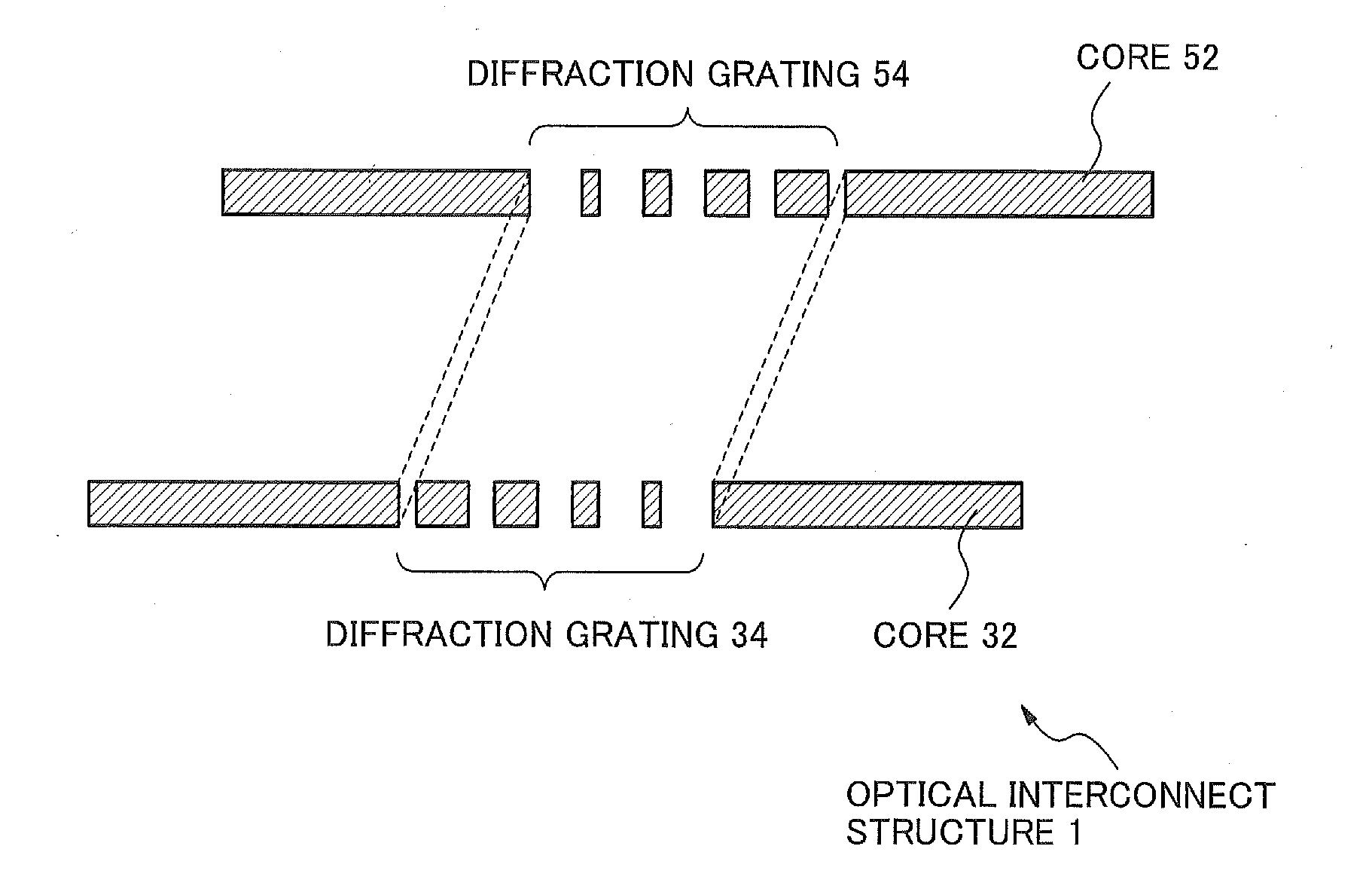
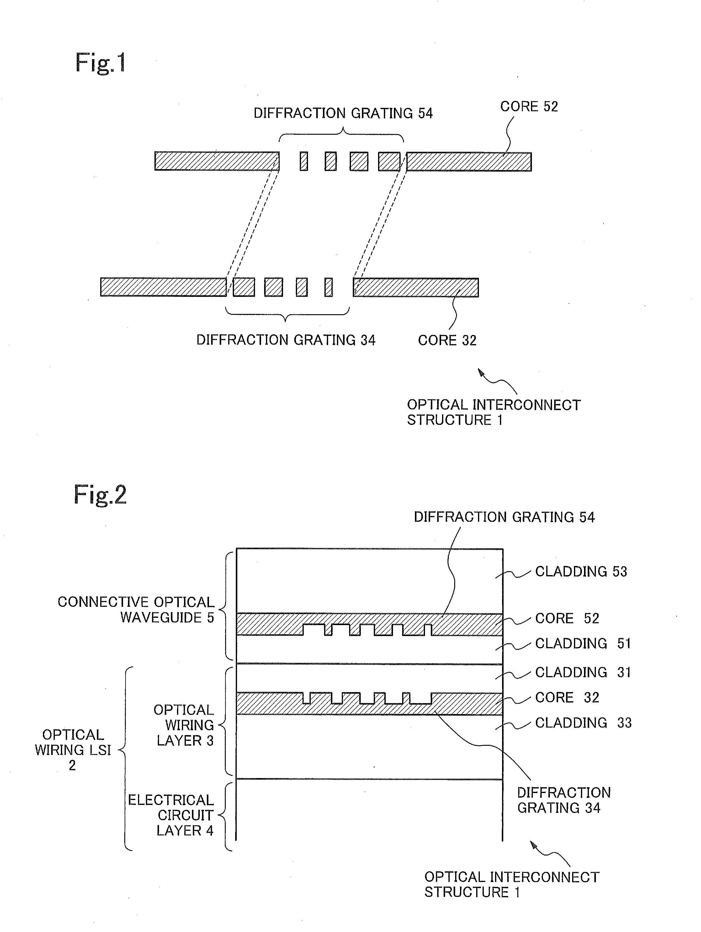
[0022]Next, a first exemplary embodiment will be described below. FIG. 1 shows a perspective view of only core layer portions extracted from an optical interconnect structure of the present exemplary embodiment. FIG. 2 shows a cross-sectional view of the optical interconnect structure 1.
[0023]As shown in FIG. 2, the optical interconnect structure 1 of the present exemplary embodiment comprises an optical wiring LSI 2 comprising an optical wiring layer 3, and also comprises a connective optical waveguide 5.
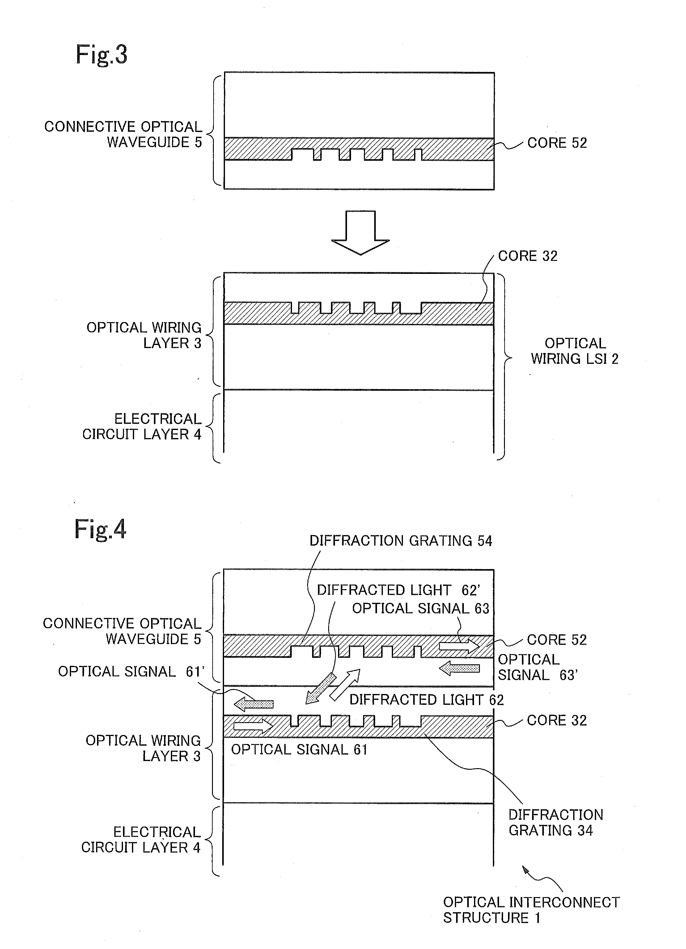
[0024]FIG. 3 is a transverse cross-sectional view showing a positional relationship between the optical wiring LSI 2 and the connective optical waveguide 5 before their connection. FIG. 4 is a transverse cross-sectional view showing a positional relationship between the optical wiring LSI 2 and the connective optical waveguide 5 after their connection.
[0025]In the optical interconnect structure 1, the detachable connective optical waveguide 5 is connected onto the optical wiring LS...
second exemplary embodiment
[0048]Next, a second exemplary embodiment will be described with reference to a drawing. FIG. 5 is a diagram showing the second exemplary embodiment, where a perspective view of only core layer portions extracted respectively from an optical wiring layer 3 and a connective optical waveguide 5 is illustrated.
[0049][Description of structure] In the present exemplary embodiment, similarly to in the first exemplary embodiment, an optical interconnect structure 1 comprises an optical wiring LSI 2 comprising an optical wiring layers 3, and also comprises a connective optical waveguide 5. The optical wiring layer 3 comprises a core 32 in which a diffraction grating 34 is formed, and the connective optical waveguide 5 comprises a core 52 in which a diffraction grating 54 is formed. Then, the diffraction gratings 34 and 54 are arranged such that at least a part of one of them faces a part of the other.
[0050]A difference of the present exemplary embodiment from the first exemplary embodiment ...
third exemplary embodiment
[0054]Next, a third exemplary embodiment will be described below.
[0055][Description of structure] In the present exemplary embodiment, similarly to in the second exemplary embodiment, an optical interconnect structure 1 comprises an optical wiring LSI 2 comprising an optical wiring layers 3, and also comprises a connective optical waveguide 5. The optical wiring layer 3 comprises a core 32 in which a diffraction grating 34 is formed, and the connective optical waveguide 5 comprises a core 52 in which a diffraction grating 54 is formed. Then, the diffraction gratings 34 and 54 are arranged such that at least a part of one of them faces a part of the other.
[0056]Further, in the present exemplary embodiment, the core 32 in the optical wiring layer 3 has a refractive index, Ncr3, equivalent to that of the core 52 in the connective optical waveguide 5, Ncr5, and claddings 31 and 33 in the optical wiring layer 3 have a refractive index, Ncl3, equivalent to that of claddings 51 and 53 in t...
PUM
 Abstract
Description
Claims
Application Information
 - R&D
- Intellectual Property
- Life Sciences
- Materials
- Tech Scout
- Unparalleled Data Quality
- Higher Quality Content
- 60% Fewer Hallucinations
Browse by: Latest US Patents, China's latest patents, Technical Efficacy Thesaurus, Application Domain, Technology Topic, Popular Technical Reports.
© 2025 PatSnap. All rights reserved.Legal|Privacy policy|Modern Slavery Act Transparency Statement|Sitemap|About US| Contact US: help@patsnap.com


