Device for recovering residual heat from exhaust gas

a technology of exhaust gas and residual heat, which is applied in the direction of heat recovery, greenhouse gas reduction, lighting and heating apparatus, etc., can solve the problems of increasing the size of the apparatus, complicated structure, stress corrosion cracking (scc) of the water pipe, etc., to prevent stress corrosion cracking, improve heat recovery efficiency, and increase the partial pressure of the vapor

Inactive Publication Date: 2013-05-23
MITSUBISHI HEAVY IND LTD
View PDF5 Cites 8 Cited by
  • Summary
  • Abstract
  • Description
  • Claims
  • Application Information

AI Technical Summary

Benefits of technology

[0030]Thus, since the flow direction of the to-be-heated water flowing in the dry economizer and the condensation economizer is provided so as to face the flow direction of the exhaust gas, the heat recovery efficiency is able to be improved.
[0031]In the present invention, the condensation economizer is provided in a downstream duct that directs the exhaust gas to flow upward, and the device is configured so that temperature of the exhaust gas amounts to condensation temperature at a vicinity of the upper part of the condensation economizer. Thus, vapor in the exhaust gas is condensed in the vicinity of the upper part of the condensation economizer, and becomes a drain. The generated drain falls down from vicinity of the upper part of the condensation economizer and comes into contact with the water pipe group constituting the condensation economizer, and thus, the outer wall of the water pipe is kept in a wet state from the upper part to the lower part. For this reason, the drying and wetting cycle is able to be prevented in the water pipe group in the condensation economizer, which is able to prevent the stress corrosion cracking.
[0032]Furthermore, when falling down from the vicinity of the upper part of the condensation economizer, since the generated drain comes into contact with the water pipe group and falls down so as to face the exhaust gas of the upward flow, it is possible to increase partial pressure of the vapor in the exhaust gas flowing in the condensation economizer. For this reason, the condensation amount in the condensation economizer is increased, the condensation efficiency rises, and the residual heat recovery rate of the exhaust gas rises.

Problems solved by technology

In the middle part, the water pipe group repeats the cooling and the heating, and thus there is a possibility that stress corrosion cracking (SCC) may occur in the water pipe.
Furthermore, in Patent Document 2, since the sensible heat transfer area and the condensation heat transfer area are alternately provided, the structure is complicated and the apparatus increases in size.
In addition, since it is feared that the position of the condensation heat transfer area is changed due to a change in boiler load, similarly to Patent Document 1, a zone is generated where the drying and the wetting are repeated, whereby there is a possibility of the stress corrosion cracking being generated.

Method used


Image

  • Device for recovering residual heat from exhaust gas
  • Device for recovering residual heat from exhaust gas
  • Device for recovering residual heat from exhaust gas

Examples


first embodiment

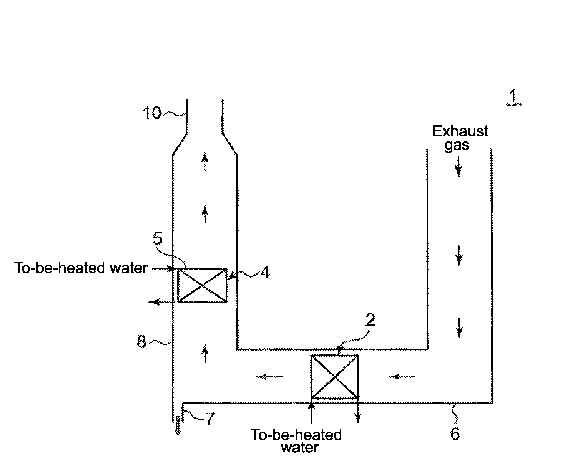
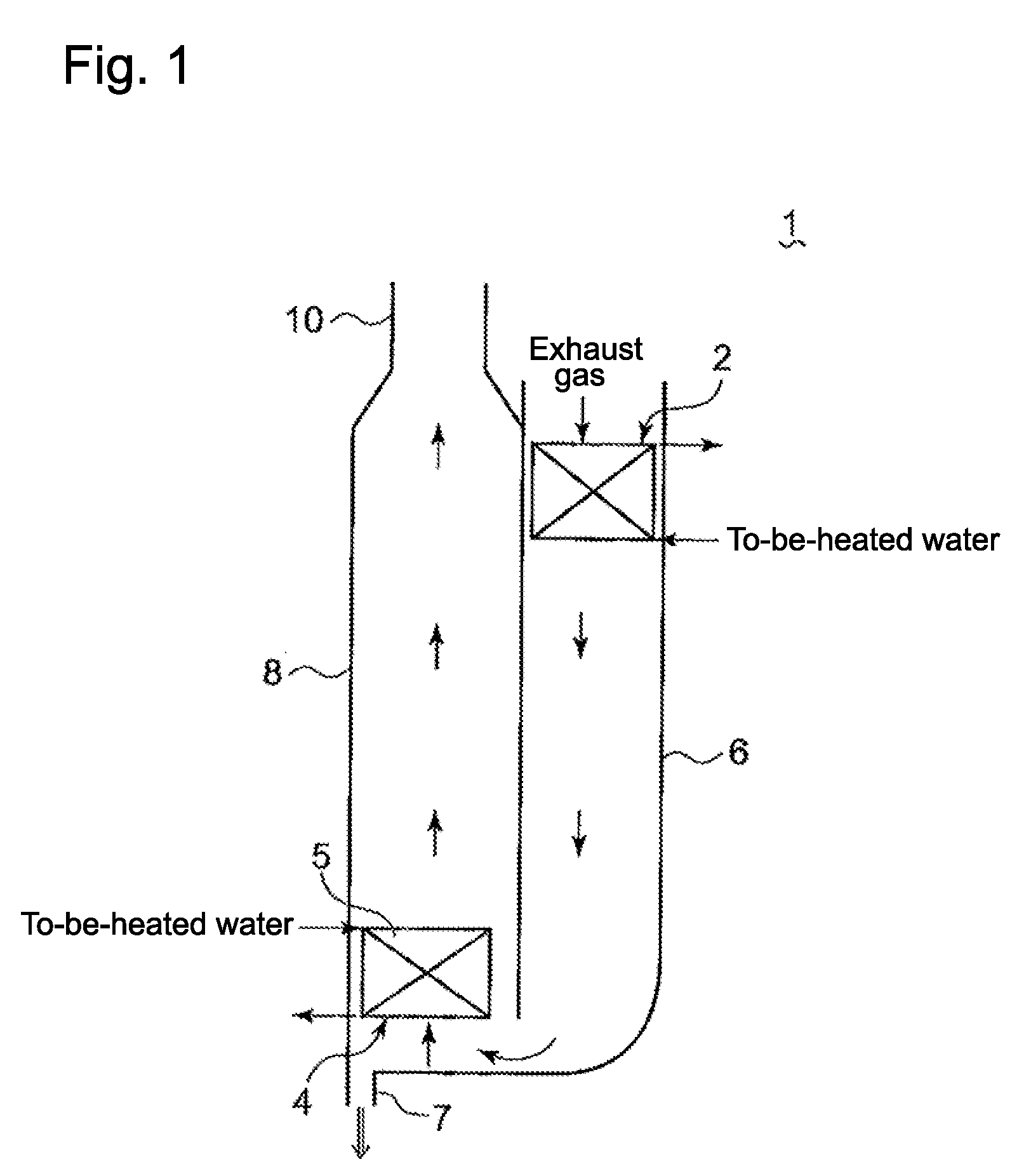
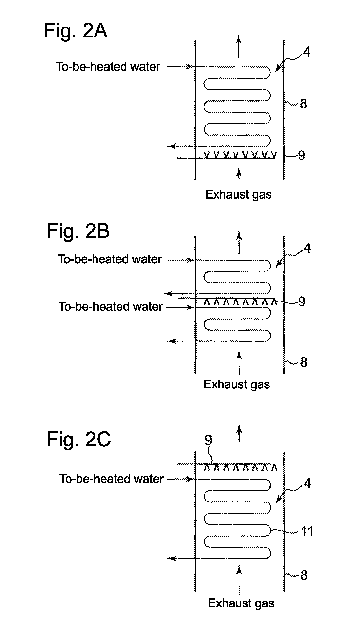
[0040]FIG. 1 is a schematic configuration diagram that illustrates an example of the device for recovering residual heat from exhaust gas according to a first embodiment of the present invention. FIG. 2 is a schematic diagram that illustrates an installation example of a spray nozzle provided at the vicinity of a condensation economizer.

[0041]The device 1 for recovering residual heat from exhaust gas according to the present invention is provided in a duct connected to a funnel 10 that discharges the exhaust gas from a boiler to the atmosphere. As shown in FIG. 1, the device 1 for recovering residual heat from exhaust gas mainly includes a dry economizer 2 and a condensation economizer 4.

[0042]The dry economizer 2 and the condensation economizer 4 include a water pipe through which the to-be-heated water (a boiler water) is circulated. A material of the water pipe preferably uses SUS316L added with molybdenum in austenitic stainless steel from the viewpoint of improving a corrosion ...

second embodiment

[0062]Next, the device for recovering residual heat from exhaust gas according to a second embodiment will be described.

[0063]FIG. 4 is a schematic configuration diagram that illustrates a device for recovering residual heat from exhaust gas according to a second embodiment.

[0064]The device 1 for recovering residual heat according to the second embodiment has the same configuration as that of the device 1 for recovering residual heat described in the first embodiment except that white smoke to be discharged from the funnel to the atmosphere is suppressed. For that reason, the detailed description of the same configuration as that of the first embodiment will be omitted.

[0065]As shown in FIG. 4, the device 1 for recovering residual heat further includes a white-smoke detector 12, a heater 14, and a heating controller 22, besides the configuration described in FIG. 1.

[0066]The white-smoke detector 12 detects the white smoke to be discharged from the funnel 10 to the atmosphere. The wh...

third embodiment

[0075]Next, a device for recovering residual heat according to a third embodiment will be described.

[0076]FIG. 5 is a schematic configuration diagram that illustrates a device for recovering residual heat from exhaust gas according to the third embodiment.

[0077]The device 1 for recovering residual heat from exhaust gas according to the third embodiment has the same configuration as the device 1 for recovering residual heat described in the second embodiment except that a bypass channel and a damper are provided instead of the gas-gas heater 14 as the heater, and thus, the detailed description of the same configuration will be omitted.

[0078]As shown in FIG. 5, the heater includes a bypass channel 28 and a damper 32. The bypass channel 28 connects the upstream duct 6 with the downstream duct 8, and joins a part of the exhaust gas of the upstream duct 6 on the downstream side of the exhaust gas flow of the condensation economizer 4. The damper 32 controls the flow rate of the exhaust g...


PUM


Abstract

A device for recovering residual heat from exhaust gas includes: a dry economizer which heats to-be-heated water by utilizing sensible heat of the exhaust gas, the dry economizer being provided in a duct extending to a funnel through which the exhaust gas is emitted to atmosphere; and a condensation economizer which heats to-be-heated water by utilizing latent heat of condensation of the exhaust gas, the condensation economizer being provided on a downstream side of the dry economizer. The duct includes an upstream duct in which the dry economizer is provided and a downstream duct connected to the upstream duct and directing the exhaust gas to flow upwardly. The condensation economizer is arranged in the downstream duct so that temperature of the exhaust gas amounts to condensation temperature at a vicinity of an upper part of the condensation economizer.

Description

BACKGROUND OF THE INVENTION[0001]1. Field of the Invention[0002]The present invention relates to a device for recovering residual heat from exhaust gas. Particularly, the present invention relates to a device for recovering residual heat from exhaust gas that includes a dry economizer which heats to-be-heated water by utilizing sensible heat of the exhaust gas, the dry economizer being provided in a duct extending to a funnel through which the exhaust gas is emitted to atmosphere; and a condensation economizer which heats to-be-heated water by utilizing latent heat of condensation of the exhaust gas, the condensation economizer being provided on the downstream side of the dry economizer.[0003]2. Description of the Related Art[0004]In related art, in a duct through which the exhaust gas from a boiler is circulated, an economizer is provided which heats a boiler water supply (to-be-heated water) using residual heat of the exhaust gas. The economizer recovers the residual heat of the e...

Claims


Application Information

Patent Timeline
Patent Type & Authority Applications(United States)
IPC IPC(8): F22D1/12
CPCF22D1/02Y02E20/363F22D1/12F23J15/06F28D19/042F24D2200/18F22D1/003Y02E20/30
Inventor ICHIHARA, TAROUTERAMOTO, KENSHUSUGITA, RYOSUKE
Owner MITSUBISHI HEAVY IND LTD
Why Eureka
Try Eureka