Hybrid porous structure, method of preparing hybrid porous structure, separation membrane including hybrid porous structure, and water treatment device including membrane

a technology of hybrid porous structure and porous structure, which is applied in the direction of membranes, separation processes, multi-stage water/sewage treatment, etc., can solve the problems of reduced driving pressure, reduced physical strength, and high physical strength of separation membranes with relatively low porosity, and achieves the effect of increasing osmotic pressur

Active Publication Date: 2013-05-30
SAMSUNG ELECTRONICS CO LTD
View PDF11 Cites 42 Cited by
  • Summary
  • Abstract
  • Description
  • Claims
  • Application Information

AI Technical Summary

Benefits of technology

[0033]The ionic polymer solution may include an anionic polymer or a cationic polymer. When the ionic polymer solution includes an anionic polymer, the ionic polymer solution may have a higher pH than pKa of the anionic polymer so as to form a coating layer having an uneven surface with protrusions and depressions in which the anionic polymers are twisted or clotted. On the other hand, the ionic polymer solution may have a lower pH than pKa of the anionic polymer so as to form a coating layer with a smooth surface (e.g., flat curved surface). When the ionic polymer solution includes a cationic polymer, the ionic polymer solution may have a lower pH than pKa of the cationic polymer so as to form a coating layer having an uneven surface with protrusions and depressions in which the cationic polymers are twisted or clotted. On the other hand, the ionic polymer solution may have a higher pH than pKa of the cationic polymer so as to form a coating layer with a smooth surface (e.g., flat curved surface).
[0034]According to yet another non-limiting embodiment, a forward osmosis water-treatment device may include a feed solution including impurities for purification; a draw solution with a higher osmotic pressure than the feed solution; a separation membrane contacting the feeding solution on one side and the draw solution on the other side; a separating system configured to separate a draw solute from the draw solution downstream from the separation membrane; and a connector configured to inject the draw solute separated from the draw solution back into the portion of the draw solution contacting the separation membrane.

Problems solved by technology

For example, a separation membrane with relatively high porosity may decrease driving pressure but may have lower physical strength.
On the contrary, a separation membrane with relatively low porosity may have higher physical strength but may increase driving pressure.

Method used


Image

  • Hybrid porous structure, method of preparing hybrid porous structure, separation membrane including hybrid porous structure, and water treatment device including membrane
  • Hybrid porous structure, method of preparing hybrid porous structure, separation membrane including hybrid porous structure, and water treatment device including membrane
  • Hybrid porous structure, method of preparing hybrid porous structure, separation membrane including hybrid porous structure, and water treatment device including membrane

Examples


example

Example 1

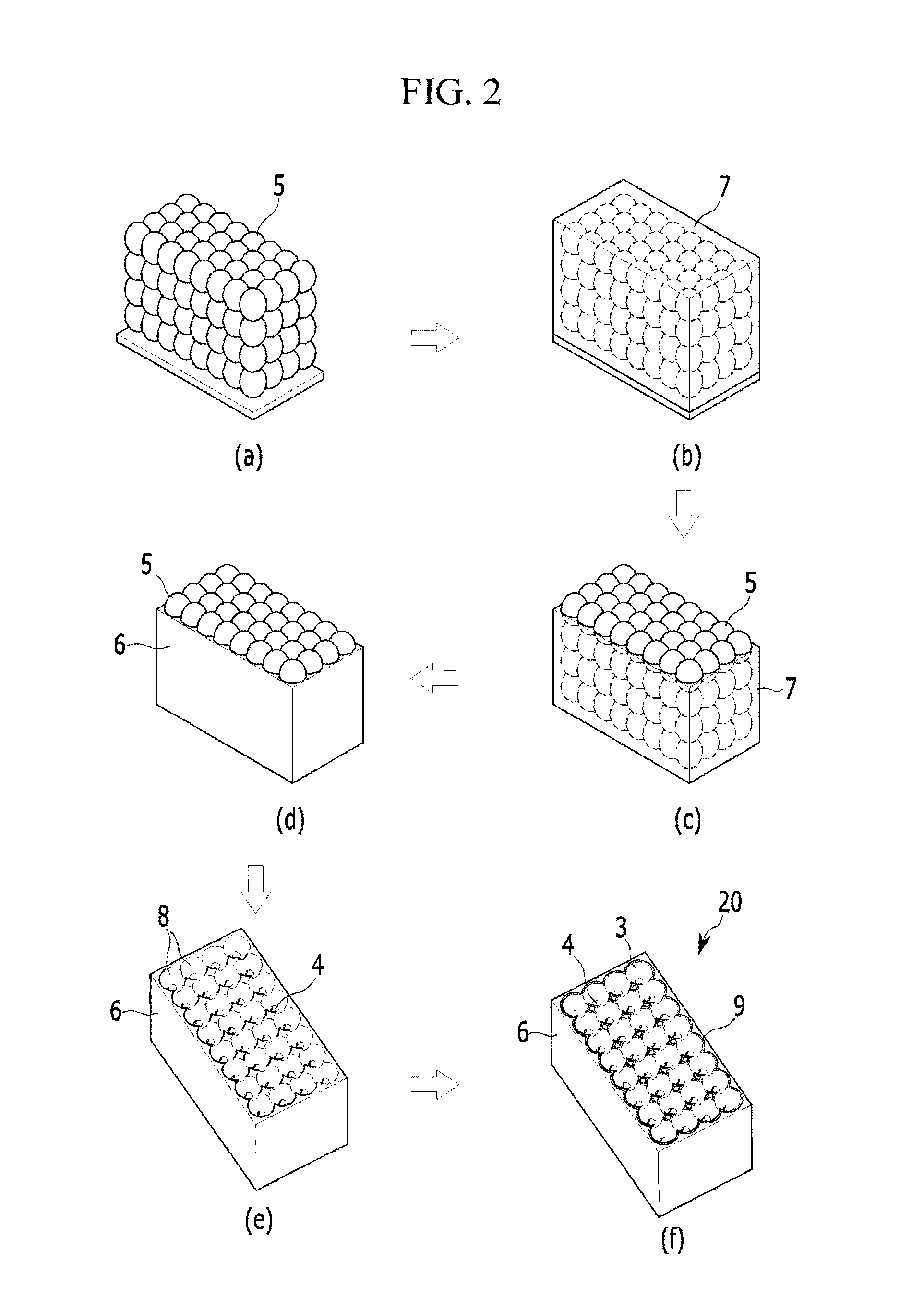
[0115]First, 800 nm-sized polystyrene nanoparticles are used to form an opal-like structure with a highly-developed crystal lattice in a sedimentation method. Then, polyurethane acrylate is injected into the opal-like structure (also referred to as an opal-shaped structure) in a spin coating method (1000 rpm, 5 min). In order to form an inverse opal-shaped free-standing thin membrane with both sides open, the surface of the opal-shaped structure is planarized by performing a spin coating method (1000 rpm, 60 sec) three times with ethanol (20 v / v %, deionized water (DI)) and removing the excess polyurethane acrylate existing on the surface thereof. Then, the inverse opal-shaped free-standing thin membrane is cured for about 2 hours and 30 minutes under ultraviolet (UV) exposure to prepare a polyurethane acrylate non-porous template with an inverse opal shape. The polyurethane acrylate non-porous template with an inverse opal shape is supported in toluene for about one hour t...

example 2

[0120]A hybrid porous structure membrane is fabricated according to the same method as Example 1, except for changing pH of the cationic and anionic polymer solutions and the number of the ionic polymer layers as provided in the following Table 1. The ionic polymer coating layers are respectively formed as laminates of a range of about 60 to about 70 layers.

[0121]FIG. 6(a) provides a cross-sectional SEM photograph of a hybrid porous structure having ionic polymer coating layer of laminate of about 60 layers, while FIG. 6(b) provides a cross-sectional SEM photograph of a hybrid porous structure having ionic polymer coating layer of laminate of about 70 layers.

example 3

[0122]A hybrid porous structure is fabricated according to the same method as Example 1, except for changing the pH of the cationic and anionic polymer solutions and the number of laminate of layers of an ionic polymer layer as provided in the following Table 1.

[0123]FIG. 7 provides a cross-sectional SEM photograph of the hybrid porous structure.


PUM

PropertyMeasurementUnit
thicknessaaaaaaaaaa
diameteraaaaaaaaaa
diameteraaaaaaaaaa

Abstract

A hybrid porous structure may include a base template and an ionic polymer coating layer within the base template. The structural framework of the base template itself is non-porous. The base template fills the gaps among a plurality of imaginary spherical bodies stacked in three-dimensions as an imaginary stack. The ionic polymer coating layer is laminated on an inner surface of the base template inside the imaginary spherical bodies. The imaginary spherical bodies may have a pore in the center which is not occupied by the ionic polymer coating layer. The hybrid porous structure may include a plurality of necks, which are openings formed in a contact part where adjacent imaginary spherical bodies contact each other. The necks may be interconnected to the pores located in the center part of the imaginary spherical bodies.

Description

CROSS-REFERENCE TO RELATED APPLICATION[0001]This application claims priority under 35 U.S.C. §119 to Korean Patent Application No. 10-2011-0126087, filed in the Korean Intellectual Property Office on Nov. 29, 2011, the entire contents of which are incorporated herein by reference.BACKGROUND[0002]1. Field[0003]This disclosure relates to a hybrid porous structure, a method of manufacturing the hybrid porous structure, a separation membrane including the hybrid porous structure, and a water treatment device including the separation membrane.[0004]2. Description of the Related Art[0005]A separation membrane including pores may be used to separate a material with a specific size. As a result, such a separation membrane may be applied to water treatment by using this property to remove pollutants. The separation membrane for water treatment may be divided into various types according to the size of the micropores (including a microfiltration membrane, an ultrafiltration membrane, a nanofi...

Claims


Application Information

Patent Timeline
Patent Type & Authority Applications(United States)
IPC IPC(8): B01D71/06B05D3/10B32B5/18
CPCB01D61/002B01D67/003B01D69/10B01D69/105B01D71/06B01D2325/16B01D2323/24B01D2323/26B01D2325/02B01D2325/14B32B5/18Y10T428/249955Y10T428/249956Y10T428/249958B01D69/06B01D69/12B01D71/82C02F1/44
Inventor KANG, HYOYOO, PIL JINHAN, SUNG SOOKIM, YOUNG HUNYEO, SEON JU
Owner SAMSUNG ELECTRONICS CO LTD
Why Eureka
Try Eureka