Dental Tools for Photo-Curing of Dental Fillings

a technology of dental fillings and dental tools, which is applied in the field of filling cavities in teeth, can solve the problems of amalgam fillings permanently weakening the brittle crystalline structure of teeth, amalgam tends to discolor, composite fillings, etc., and achieves the effects of reducing the occurrence of weakening the bonding, reducing the voids in the filling, and safe manipulation

Inactive Publication Date: 2013-05-30
SAPPHIRE TECH
View PDF21 Cites 9 Cited by
  • Summary
  • Abstract
  • Description
  • Claims
  • Application Information

AI Technical Summary

Benefits of technology

[0015]The present invention provides dental tools that can be safely used to manipulate and compact composite polymer fillings not only prior to the curing process but during the curing process. The dental tool does not distort or reflect the transmission of ultraviolet or visible light used to cure the polymers in the cavity. The ability on the dental tool to be used during the photo-curing process enables the c

Problems solved by technology

Also, amalgam fillings permanently weaken the brittle crystalline structure of the tooth as the void left by cavity preparation is a permanent removal of integral material strength for the tooth, wherein the amalgam filling does not replace the void with a structurally integral element as the amalgam does not bond with the tooth as it must be retained with features to hold it in the tooth, further amalgam tends to discolor over time as well as being undesirably noticeable or visible, being typically bright silver in color that is in stark contrast to the near white tooth enamel color.
However, negatives are that the placement of the composite fillings into the cavities of the tooth can be difficult in order to eliminate any air pocket porosity or other voids where bacteria might be able to grow, or causing increased tooth hot and cold sensitivity, and further causing weakness in the combined tooth/composite structure.
These fillings have a variety of problems associated with them and typically are not as commonly used as composites which are becoming the de-facto preferred standard tooth filling.
The composite polymer will shrink some during the photo-polymerization process, being typically about 2-6% which is undesirable in increasing the risk of air pocket porosity in the composite and weakened bonding as between the composite and the prepared tooth cavity.
This results in the need for multiple thin layers of the composite polymer.
Also, the polymer must be manipulated into the prepared cavity which is typically difficult to reach and relatively small in volume to ensure that no voids are created in the filling, all of which requires about 50% more time usually in completing the tooth filling with composites as compared to the prior art amalgam fillings that typically require less time to complete the tooth filling.
The composite filling material curing light optimally should be positioned as close as possible to the composite material for maximum effectiveness, being a difficult task

Method used


Image

  • Dental Tools for Photo-Curing of Dental Fillings
  • Dental Tools for Photo-Curing of Dental Fillings
  • Dental Tools for Photo-Curing of Dental Fillings

Examples


embodiment 50

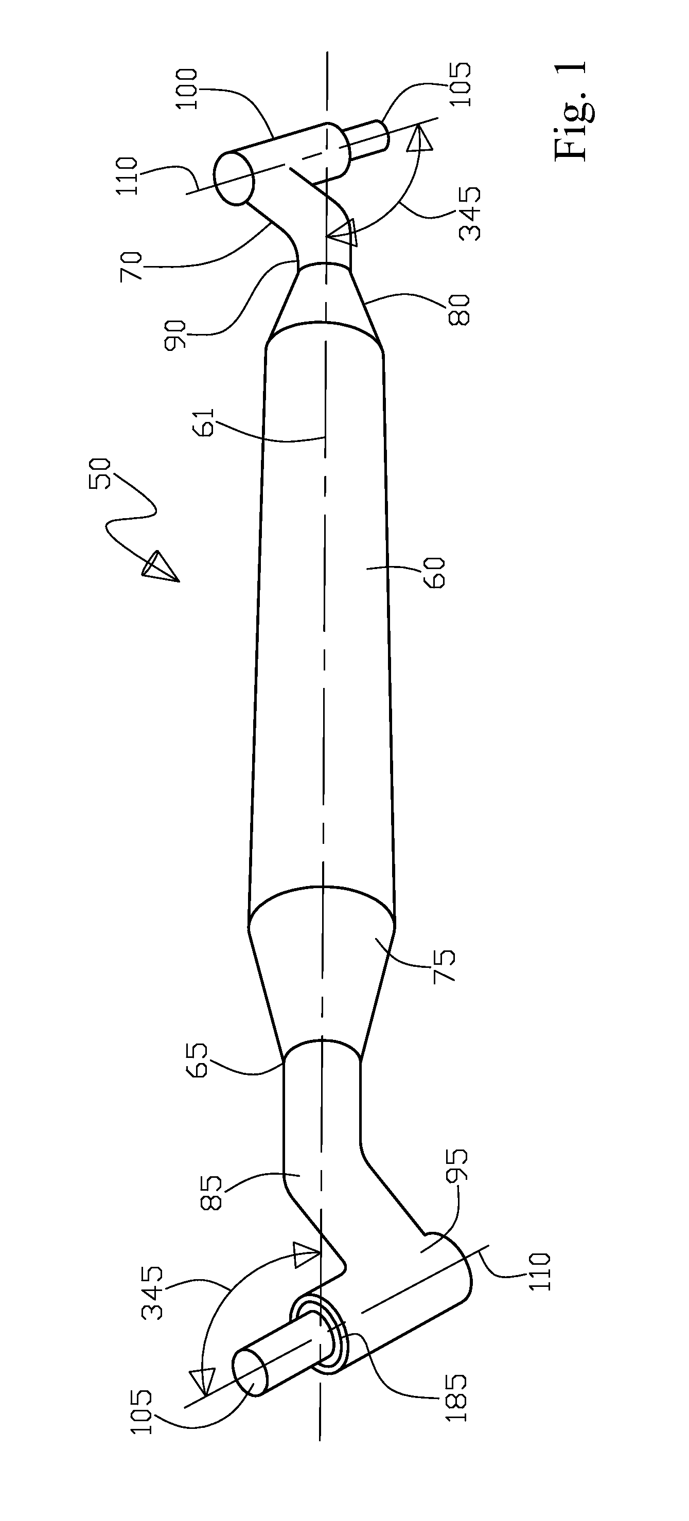
[0185]The dental tool 50 includes a central gripping member 60 with a first tool end portion 65 and an opposing second tool portion end 70. The central gripping member 60 can be formed of suitable materials, preferably a material that can be easily sterilized and that does not degrade under ultraviolet light. In the preferred embodiment 50, the central gripping member 60 is formed of a high strength plastic with knurled portions for ease of gripping. Alternatively, the gripping member 60 could be formed from stainless steel, aluminum or other suitable materials.

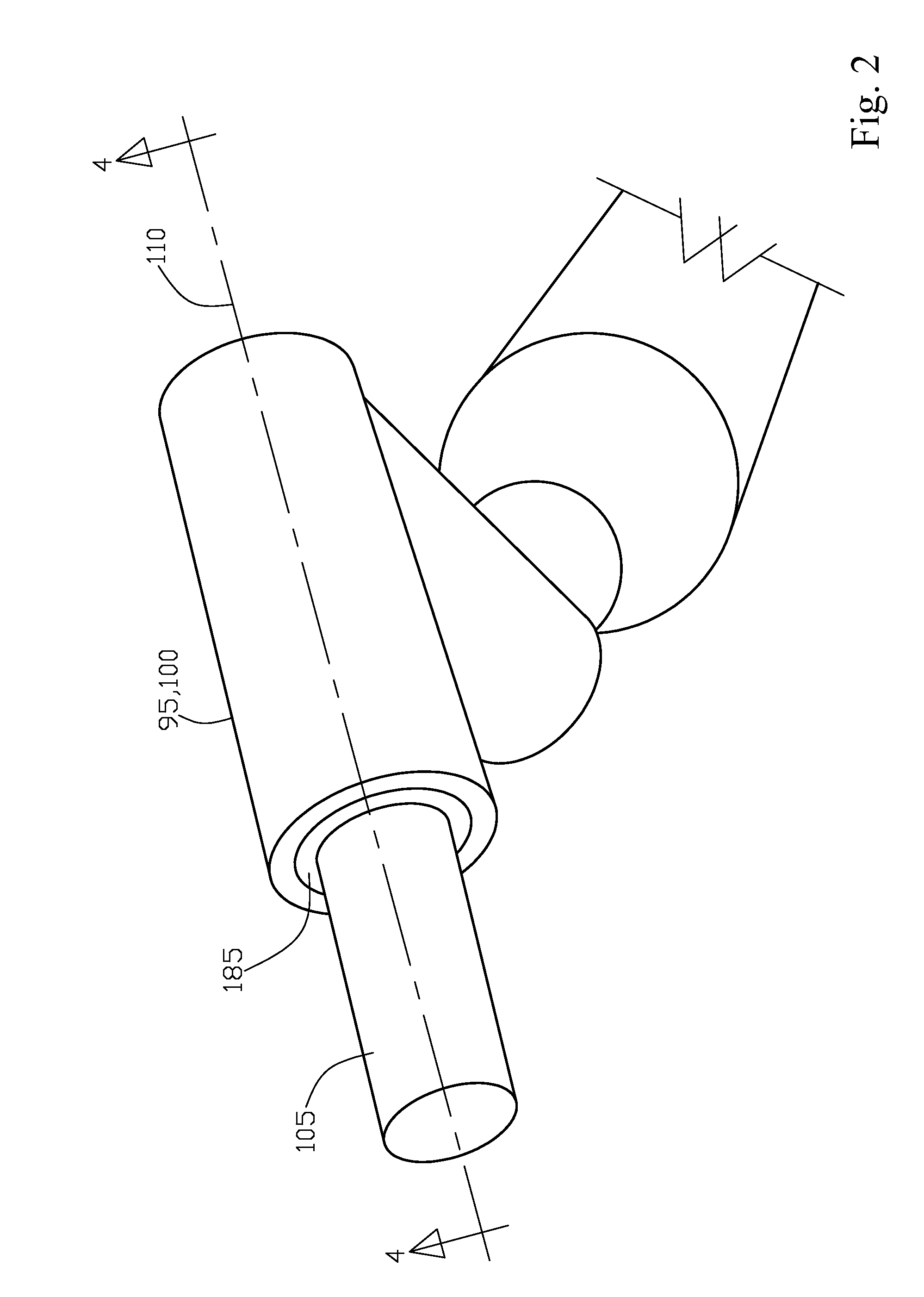
[0186]The dental tool 50, of this preferred embodiment, is illustrated with the first tool end portion 65 and the opposing second tool portion end 70. It is to be expressly understood that the tool could also include a single tool 105 end as well. The tool end 65 of this preferred embodiment includes an extended first end 75 with a reduced diameter. This reduced diameter portion 75 includes a first portion 85 that extends out...

embodiment 55

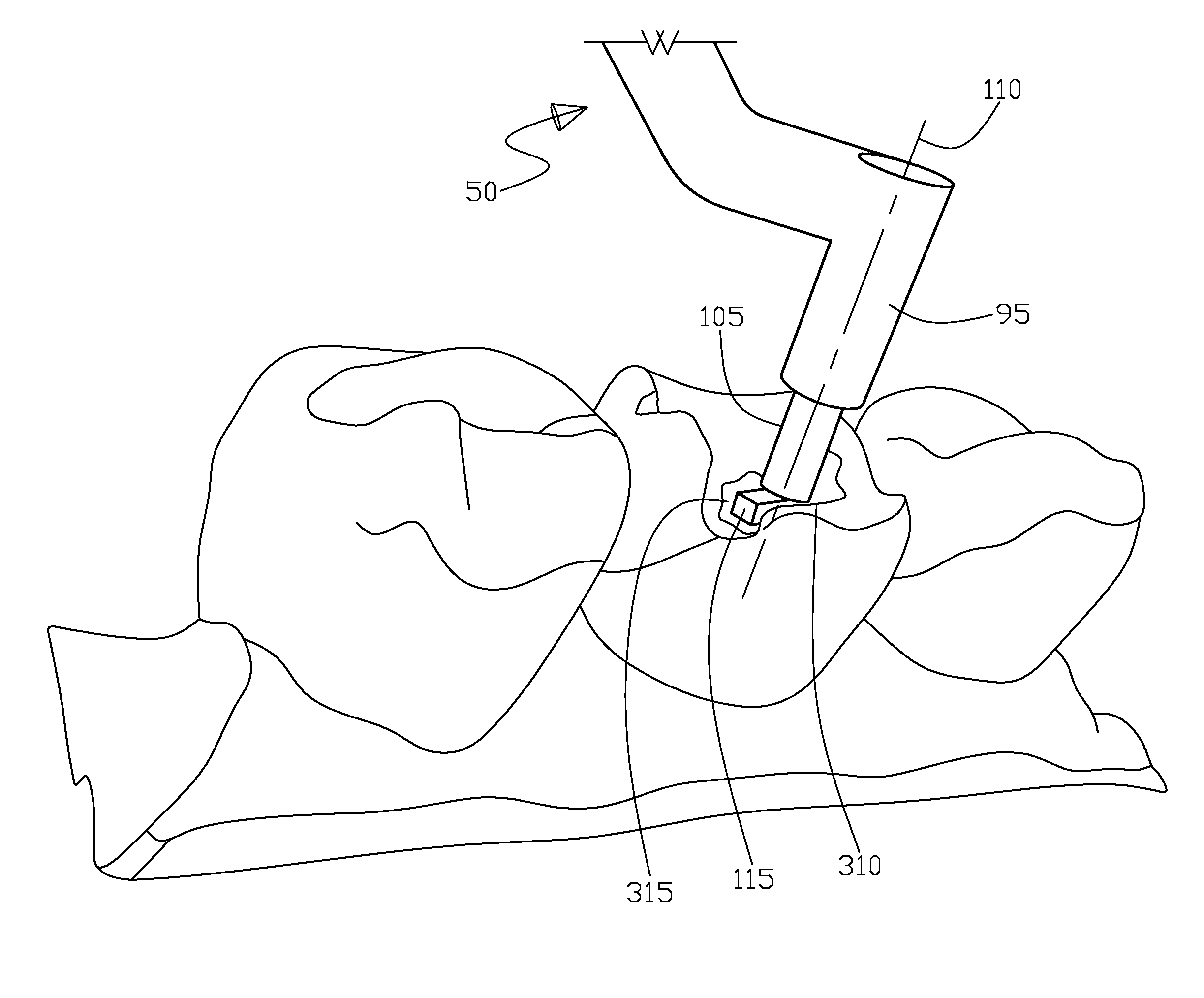
[0202]Looking in particular at FIGS. 23 through 27, as the alternative embodiment 55 is shown for the combined dental tool assembly 50 and the photo-curing light apparatus 250 further making this process of composite 315 photo-curing quicker, easier, and more efficient. As it is important to have the photo-curing light transmission 260 as close as possible to the composite material 315 and to minimize the “crowding” in the patient's 300 mouth 305 by having the light transmission 260 from light generating apparatus 250 travel therethrough the tool 55 itself or more specifically through the grip portion 60 allowing a one handed operation for the dentist 320 and more accurate photo-curing positioning. This results in minimizing any chance of voids 316 or porosity 316 in the cured composite 315 for a high quality filling with more structural integrity in the filled tooth, and in addition less time for the patient 300 to have tools in their mouth 305. Note that it is also preferable to h...


PUM

PropertyMeasurementUnit
Lengthaaaaaaaaaa
Fractionaaaaaaaaaa
Pressureaaaaaaaaaa

Abstract

A dental tool for use in photo-cured filling processes. The dental tool includes a tool tip formed from a material that allows the transmission of ultraviolet and visible light wavelengths through the tool tip without significant distortion or reflection. The material is also relatively high strength so not to shatter or break during use. The fill material will also not easily adhere to the tool. The material of a preferred embodiment is sapphire. The tool is able to continue to compact and shape the fill material while the composite polymer fill material is undergoing photo-curing. The light beam used for photo-curing is able to safely pass through the tool without the risk of damage to the surrounding tissue from reflection or distortion of the light beam.

Description

RELATED APPLICATIONS[0001]This is a continuation in part (CIP) patent application of U.S. patent application Ser. No. 13 / 293,948 filed on Nov. 10, 2011 by Alan Wong et al. of Federal Heights, Colo., US, that is a continuation in part (CIP) patent application of U.S. patent application Ser. No. 13 / 086,057 filed on Apr. 13, 2011 by Alan Wong et al. of Federal Heights, Colo., US that is a continuation in part (CIP) patent application of U.S. patent application Ser. No. 12 / 763,159 filed on Apr. 19, 2010 by Alan Wong of Federal Heights, Colo., US.TECHNICAL FIELD[0002]The present invention generally relates to filling cavities in teeth for the dental arts. More particularly, the present invention is a dental tool having a light transmittable tip portion to accommodate the transmission of light used for photo curing a composite filling while the dental tool tip portion concurrently forms the composite into a desired position simultaneously with the curing light transmitted therethrough the...

Claims


Application Information

Patent Timeline
IPC IPC(8): A61C5/04A61C13/15
CPCA61C5/045G02B6/3624A61C3/08A61C19/004Y10T428/24752B32B7/12B32B15/08B32B15/18B32B18/00B32B37/1284B32B37/142B32B37/18B32B38/0008B32B38/0012B32B38/162B32B2038/0016B32B2307/746B32B2311/30B32B2315/02
Inventor WONG, ALANROSEN, HOWARD STEVEN
Owner SAPPHIRE TECH
Why Eureka
Try Eureka