Electroosmotic pump and method of use thereof

a technology of electro-osmotic pump and pump body, which is applied in the direction of positive displacement liquid engine, separation process, filtration separation, etc., can solve the problems of viscous drag, membrane pump pressure and flow limitations, and conventional mechanical pump reliability issues, etc., to achieve high electric field strength, simple fabrication technique, and high efficiency

Inactive Publication Date: 2013-06-20
GENERAL ELECTRIC CO
View PDF10 Cites 21 Cited by
  • Summary
  • Abstract
  • Description
  • Claims
  • Application Information

AI Technical Summary

Benefits of technology

[0008]Accurately controlled electrode spacing within a thick and dense network of pores may be a solution for maintaining high electric field strength at low running voltages. The EOPs, described herein, comprising a plurality of membranes and electrodes may solve the above mentioned problem and generate a high pressure even at a lower applied voltage using a simple fabrication technique.

Problems solved by technology

Generally, the conventional mechanical pumps have issues with reliability of the moving pump-components.
Application of an electric field across a porous membrane structure of an EOP results in a movement of the electric double layer, which results viscous drag.
However, such single membrane pumps have pressure and flow limitations, such that application of a few volts generate pumping pressure of less than 1 PSI.
However, there is no current solution for an arrangement of membranes and electrodes in an EOP, such that the high pressure may be accomplished at low running voltages without changing the electric field strength across the individual pores.
In addition, standard methods (e.g. hydrolyzing metal electrodes) of generating ionic currents within the EOPs have detrimental effects on the pump operation, due to the release of gas during pumping.
The low pressure constraint remains a limiting factor for practical utility of low-voltage EOPs.
Still, the need for self-containment in analytical, biomedical, pharmaceutical, environmental, and security monitoring applications remains a great challenge, and battery-driven EOPs may serve to replace the limiting control equipment required to run devices, such as high voltage power or pressure supplies.
Maintaining high electric field strength, while using low running voltages are two conflicting requirements, which are difficult to accomplish through conventional EOPs.

Method used


Image

  • Electroosmotic pump and method of use thereof
  • Electroosmotic pump and method of use thereof
  • Electroosmotic pump and method of use thereof

Examples


example 1

Fabrication of EOPs

[0071]For this example, the need for metallization of each electroosmotic membrane in the EOP stack, assembly and handling of the electroosmotic membranes in a disposable cartridge, and manufacturing cost and fragility of the nanoporous membranes, were the primary challenges.

[0072]Materials: The Anodisc® membranes are an in-house product (GE Healthcare), which are available in a package of 100 membranes. The silica membranes were created in-house by coating GE's Anodisc® product with SiO2 using either treatment in a sol-gel solution or deposition within an atomic layer deposition chamber. Silica sol gel was produced using raw materials from Sigma Aldrich, including TEOS (Tetraethyl orthosilicate), CAT#86578-250 ml. ALD coating was performed using tris (tert-butoxy) silanol and trimethyl-aluminum as the precursors. Pt, Ag or Au electrodes were purchased from Good-fellow Cambridge Limited. The Anodisc® membranes are used as bare Anodisc® and also after the silica tr...

example 2

Determination of Stall Pressure by Increasing Number of Membranes

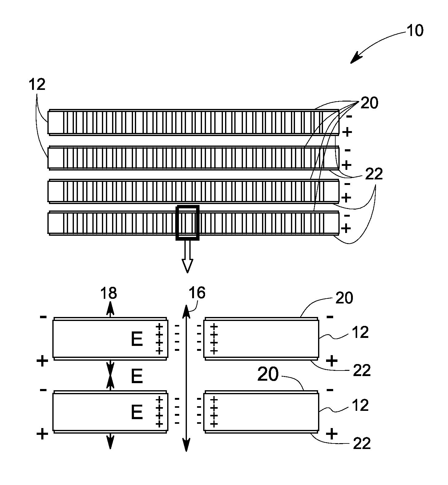
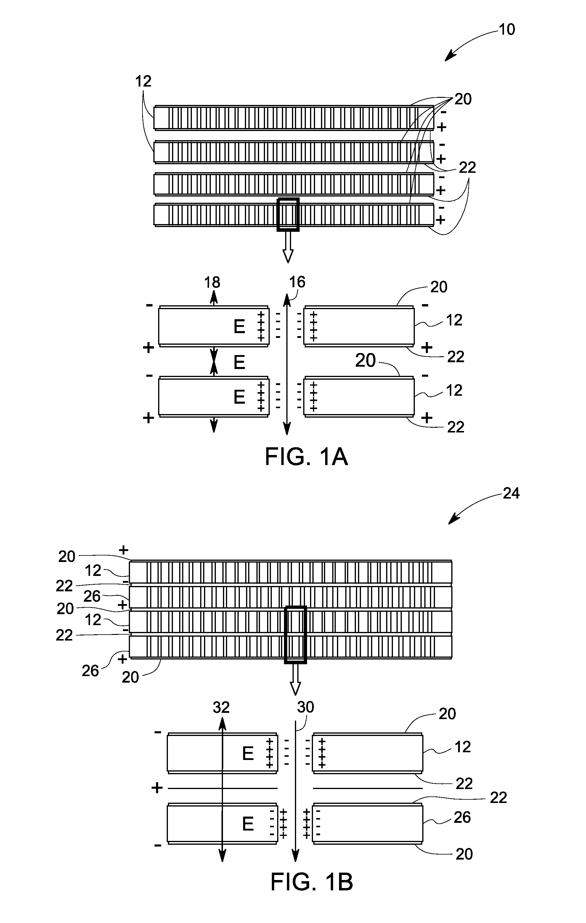
[0076]Experimental results were generated measuring the stall pressure of a single Anodisc® EOP, and a double stack membrane using low-voltage, high pressure EOPs. Flow rates were measured using a commercial MEMS flow sensor as increased back pressure was applied to the pump. There was a 2× increase in pumping pressure within the double stack membrane, when compared to single membrane EOP, as shown in FIG. 3. The pumping pressures could be tuned to application-specific values based on the intelligent assembly scheme, as shown in FIG. 1B. The flow rates were measured using a commercial MEMS flow sensor, Sensirion CMOSENS LG16-1000D, after the increased pressure load was applied to the pump. The pumping pressure may be increased or decreased according to the pressure requirement for specific applications by increasing or decreasing the number of membranes in the EOP.

example 3

EOP Operation Using Various Electrode Materials

[0077]Most electroosmotic pumps work by passing hydrolyzed ions at the surface of the metal electrodes, thus releasing hydrogen and oxygen gas at the opposite ends of the nanopores of the membranes as described in FIG. 5A-5C. In three different EOPs, three different electrodes were selected. In the first example, a Pt electrode was used where a standard hydrolysis reaction took place using a standard hydrolysis driven pump. The flow rate is comparatively less in case of this EOP with Pt electrodes. The advantage of this EOP is the use of an inert electrode and standard pump configuration. Still, gas accumulation even at low driving voltages induces bubble formation and pH fluctuation, which is an increased burden in the dense nanoporous stacks, as shown in FIG. 5A. In the second example, silver oxide was used as the metal oxide electrode, as shown in FIG. 5B, where the redox reactions took place on the electrode surface which minimized ...


PUM

PropertyMeasurementUnit
electric fieldaaaaaaaaaa
diameteraaaaaaaaaa
thicknessaaaaaaaaaa

Abstract

An electroosmotic pump comprises a plurality of membranes comprising one or more positive electroosmotic membranes and one or more negative electroosmotic membranes, a plurality of electrodes comprising cathodes and anodes, and a power source. Each of the positive electroosmotic membranes and negative electroosmotic membranes are disposed alternatively and wherein at least one of the cathodes is disposed on one side of one of the membranes and at least one of the anodes is disposed on other side of the membrane. At least one of the cathodes or anodes is disposed between a positive electroosmotic membrane and negative electroosmotic membrane.

Description

STATEMENT REGARDING FEDERALLY SPONSORED RESEARCH & DEVELOPMENT[0001]This invention was made with Government support under contract number HDTRA1-10-C-0033 awarded by the Defense Threat Reduction Agency. The Government has certain rights in the invention.FIELD[0002]The invention relates to a non-mechanical pump, and more particularly to an electroosmotic pump (EOP) that generates high pressure using comparatively lower voltage. The invention is further associated with methods for using the EOP.BACKGROUND[0003]Pumps can be classified into mechanical and non-mechanical varieties. Generally, the conventional mechanical pumps have issues with reliability of the moving pump-components. Electrokinetic pumps, on the other hand, contain no moving parts, making them suitable for a variety of applications, including fluid movement in microanalytical systems. Electroosmotic pumps (EOPs) are one of the most represented class of these pumps, and provide fluid flow due to movement of an electric d...

Claims


Application Information

Patent Timeline
Patent Type & Authority Applications(United States)
IPC IPC(8): F04B19/04
CPCF04B19/04F04B19/006
Inventor PULEO, CHRISTOPHER MICHAELKEIMEL, CHRISTOPHER FREDCHEN, XIAOHUILENIGK, RALFGALLIGAN, CRAIG PATRICKMILLER, TODD FREDERICK
Owner GENERAL ELECTRIC CO
Why Eureka
Try Eureka