

All-optical method and system for generating ultrashort charged particle beam
Patent Information
- Authority / Receiving Office
- US · United States
- Current Assignee / Owner
- INSTITUT NATIONAL DE LA RECHERCHE SCIENTIFIQUE
- Publication Date
- 2013-06-27
Smart Images
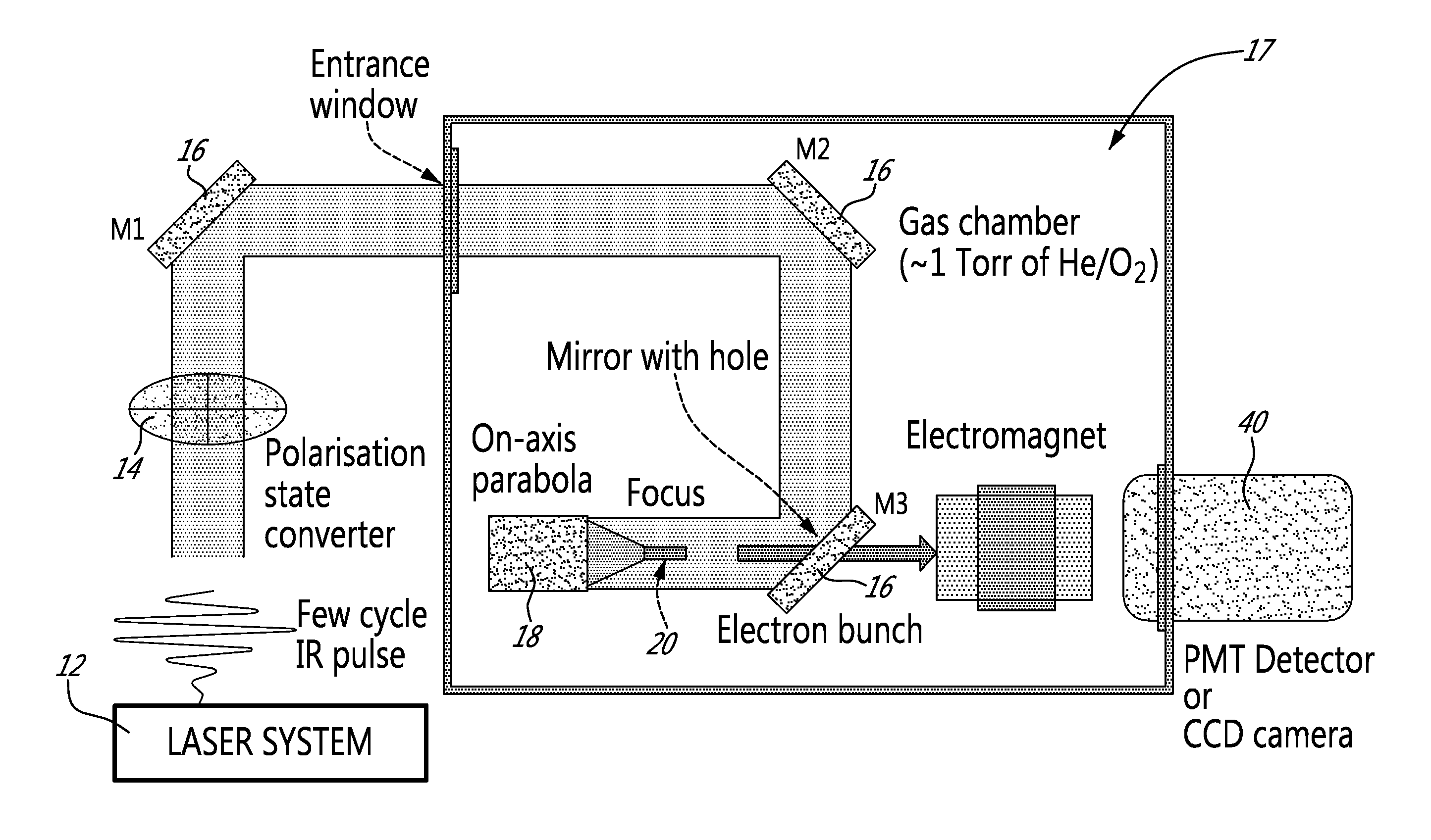
Figure 1 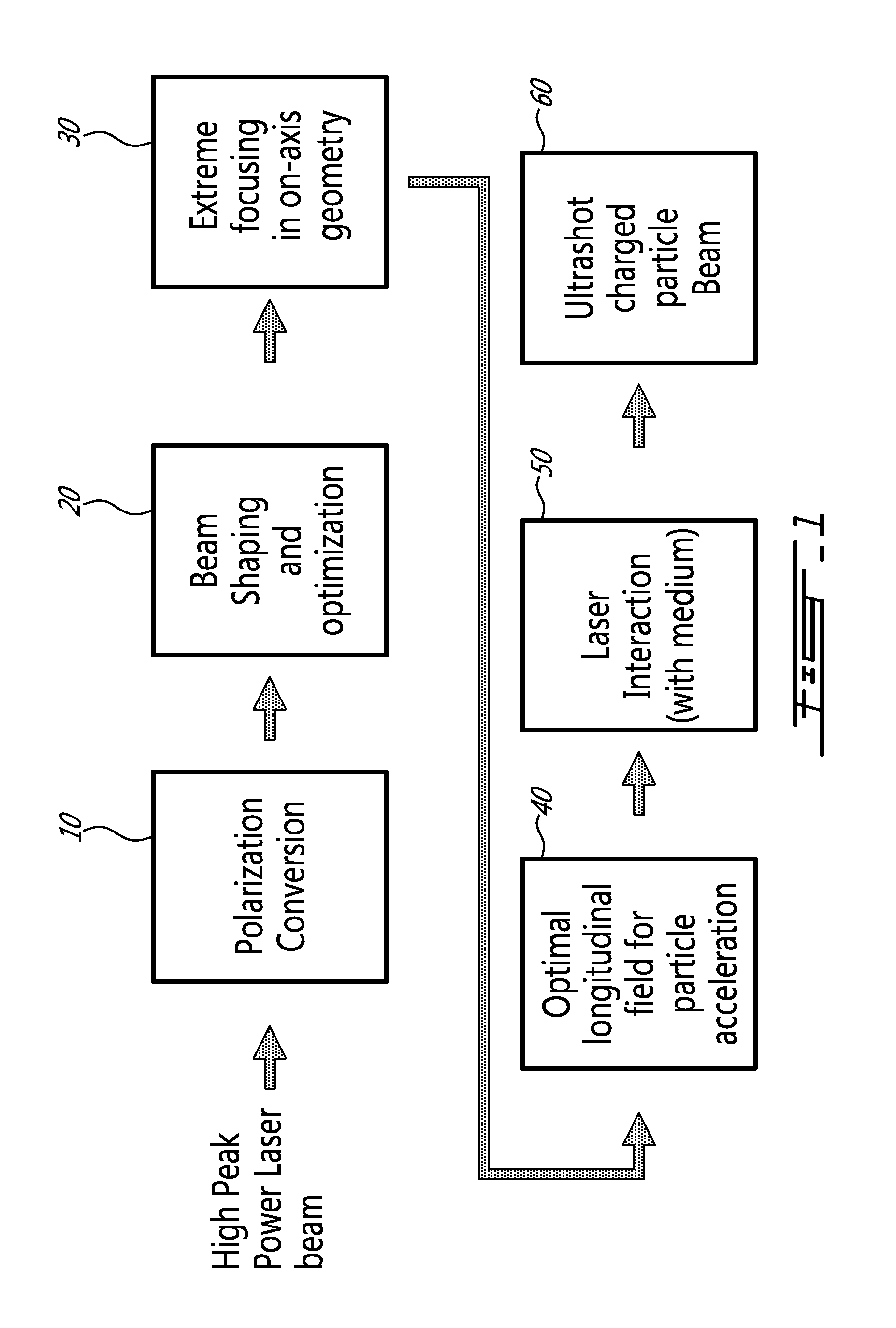
Figure 2 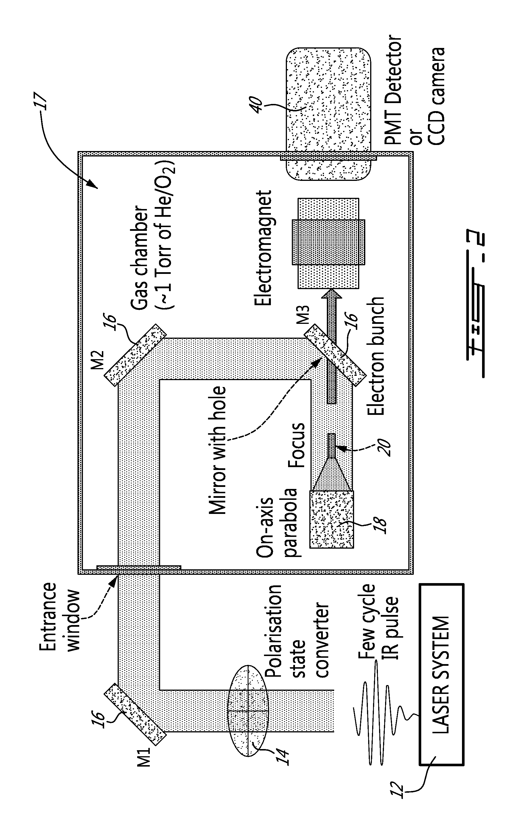
Figure 3
Abstract
Description
CROSS REFERENCE TO RELATED APPLICATIONS
[0001] This application claims benefit of U.S. provisional application Ser. No. 61 / 579,727, filed on Dec. 23, 2011. All documents above are incorporated herein in their entirety by reference.FIELD OF THE INVENTION
[0002] The present invention relates to the generation of ultrashort charged particle beam. More specifically, the present invention is concerned with an all-optical method and system for generating ultrashort charged particle beam.BACKGROUND OF THE INVENTION
[0003] Production of ultrashort electron bunches is needed in a number of applications, ranging from time-resolved electron microscopy to free-electron laser injection.
[0004] An ultrashort electron beam can be generated by many methods, including for example direct field vacuum acceleration, Wakefield acceleration and high power longitudinal field acceleration.
[0005] Theoretical studies on high power longitudinal field acceleration suggest using a radially polarized laser beam from an e...