Thus, even in the event of damage to the input sensor, absolute information, certainly rough, is maintained.
Nevertheless, the position information issuing from the diametrally magnetised input sensor is not always sufficiently precise for a critical application such as that of a
steering column since, over 360° of detection angle, it is not possible to achieve precision of very much less than + / −1° with a
contactless sensor, compatible with manufacturing constraints and robustness of large-volume applications.
Nevertheless, the solutions as described in this application suffer from both an excessive space requirement and the fact that it is impossible to meet all the specifications in terms of precision of the applications concerned.
They are in addition solely illustrated with the use of 2 magnetoresistive sensors of the AMR type for the two magnetosensitive sensors, which restricts the possibilities.
This solution is in fact bulky, as attested to by the figures illustrating the configurations proposed.
This is because, in two of the three cases presented the motion conversion and the secondary sensor are dissociated from the main magnet, leading to the use of two distinct printed circuits and therefore to an additional cost and an increase in the size of the structure.
Thus this solution cannot be easily integrated in other mecatronic devices (motor, sensor, etc.) for reasons of excessive space requirement.
The third configuration proposes the integration of one of the gears of the
gear train directly on the main rotor, but then again the axial space requirement is not optimised since the shaft of the secondary rotor is orthogonal to that of the main rotor.
Now, though they are well suited to magnet configurations referred to as “shaft end”, as is the case with the secondary sensor when the probe is positioned on the magnet rotation shaft, their use for configurations outside the axis of revolution of a magnet, such as integrated in the main rotor, has the drawback of constituting a solution having substantial dimensional limits, as will be explained below.
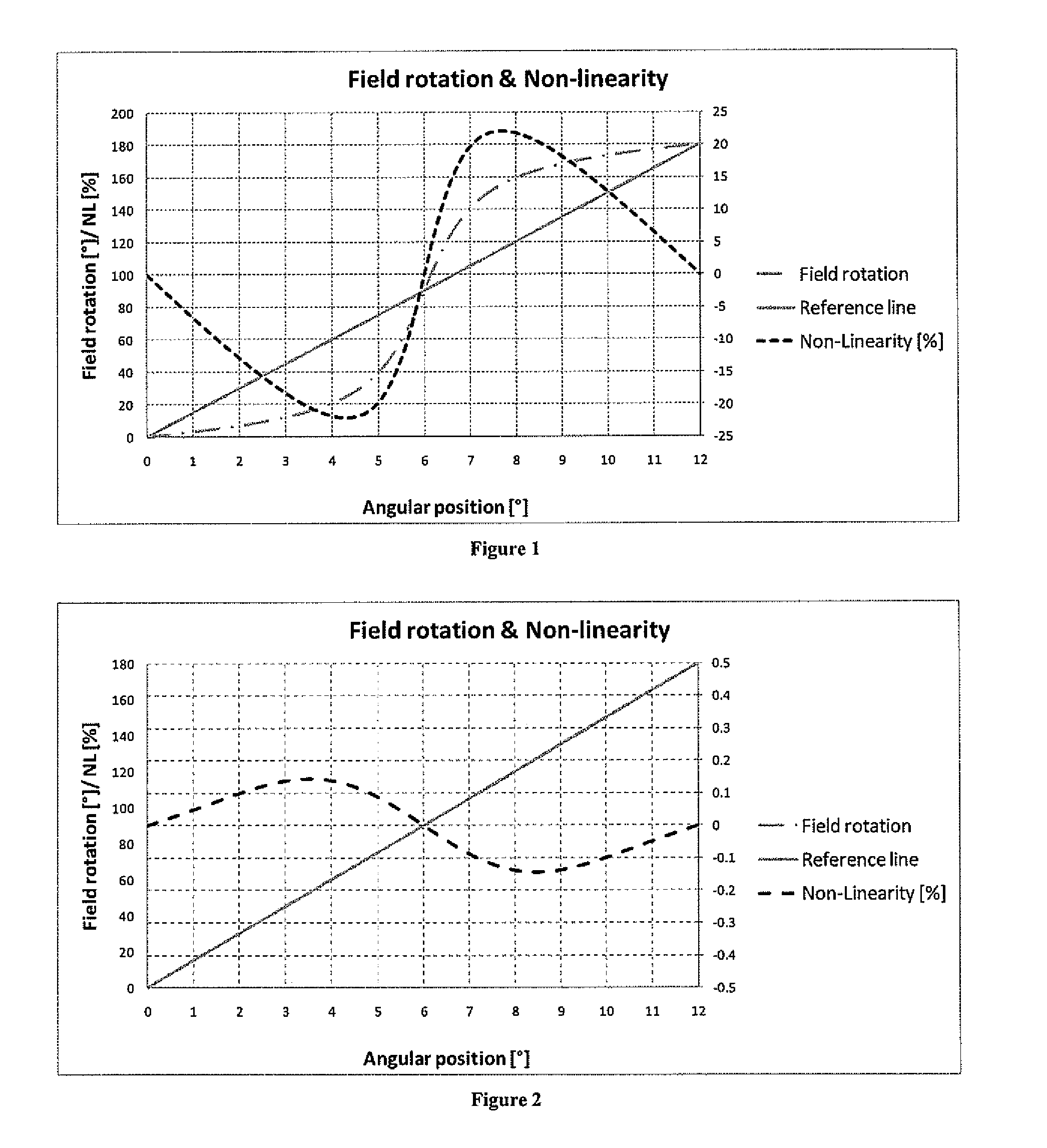
Since the variation in magnetic angle is not linear as a function of the displacement, the result is an
angular error, since the magnetoresistive elements (of the AMR type) as described generate, via a physical variation in their resistance, an output
signal directly proportional to the rotation of the
magnetic field in a plane with a periodicity of 180°.
These defects in the signals have several origins: lack of sensitivity of the sensors, lack of magnetisation, distortions caused by the proximity of the sensor to the surface of the magnet, distortions caused by the proximity of a secondary magnet as is the case in the solution or quite simply
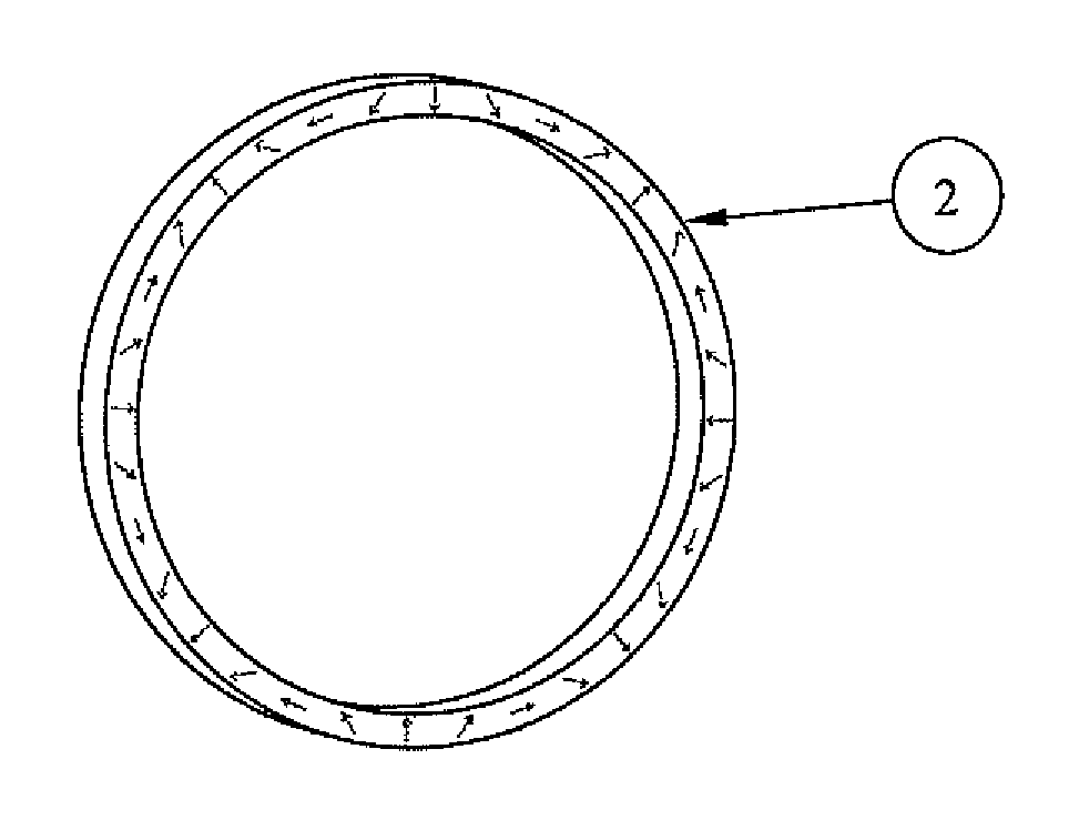
edge effects that a ring has since it is not infinitely long.
The latter require a computing capacity that must be allocated in the
processing electronics, which is detrimental.
Other configurations tend towards this magnetic equilibrium, which gives a
linear variation in the angle of the
magnetic field, but all have a drawback.
Thus a multipole rotor the geometry of which is characterised by a small
diameter will result in a mechanical incompatibility with the
diameter of the shaft of the application the position of which must be detected.
The major drawback is that this requires positioning the probe of the main sensor at a very precise distance from the mid-plane of the magnet for the purpose of tending towards equilibrium of the axial and tangential components procuring a
linear variation in the magnetic angle during the variation in the mechanical angle.
Such a sensor is therefore not very robust under axial and radial clearances and the
magnetic flux used by this type of configuration is weak since it is essentially based on the use of a leakage flux with regard to the axial component and requires a magnet
remanence typical of a high-energy magnet in order to supply an acceptable flux.
Moreover, this offset finally requires the main sensor and the secondary magnet to be closer, which accentuates the imprecision of the sensor because of the magnetic interference caused by the secondary magnet on the main sensor.
The result is then a sensor configuration that is bulky and expensive, such as the one described in the solution, namely the use of two printed circuits.
It should also be emphasised that the use of a large number of pole pairs on the main sensor as required by the solution results in an
electrical frequency seen by the sensor, when the rotary shaft is rotating, which may cause significant slip between the position indicated by the
electronics and the actual position or a loss of resolution because of the limitations in bandwidth of the
processing circuits used.
Moreover, the greater the number of poles, the more difficult it will be to obtain a precise absolute position on this type of multi-turn sensor.
However, the secondary sensor must give the position over + / −1 turn (+ / −360°), which gives rise, for a sensor with a precision of + / −0.5%, an error of + / −3.6° in the input angular position.
If the magnetic and mechanical
hysteresis of the secondary sensor is added to this error, the risk of losing the absolute information is then very great.
If it is wished to give the secondary sensor its absolute function again, then it would have to have a precision of less than + / −0.34%, which means that a multipole ring with 20 poles would be required, which does not make it possible to approach a precise main sensor for the reasons mentioned above.
A major defect of the solution is therefore either the great precision that is required of the secondary sensor in the aforementioned example because of the necessity for the main magnet to have a large number of pairs of poles, or a small number of pairs of poles if it is wished to reduce this requirement for precision on the secondary sensor.
It is therefore very difficult to maintain such precision in environments typical of those of a vehicle.
A person skilled in the art is then led to the second option but this does not make it possible to approach generic configurations of a main sensor that are precise unless the
diameter of the ring is reduced or the detection air gap is increased, which then takes us back to the previous issues.
Firstly, it is bulky since it in fact consists of two distinct sensors, one being placed above the other.
Secondly the absolute position of the multi-turn
position sensor is achieved via a discrete motion converter that does not make it possible to maintain an absolute position of the input shaft in the event of a fault on the main sensor.
In the
patent application WO 2009 / 047401, even if the problem of the discrete measurement of the multi-turn position is solved, the association of the two sensors remains bulky since it is achieved by stacking the
torque sensor function and multi-turn
position sensor and, the main sensor being of the absolute type over one turn, it consists of a bipolar magnet that generates a high
magnetic disturbance on the Hall sensors constituting the
torque sensor also conferring a lack of precision on the whole.
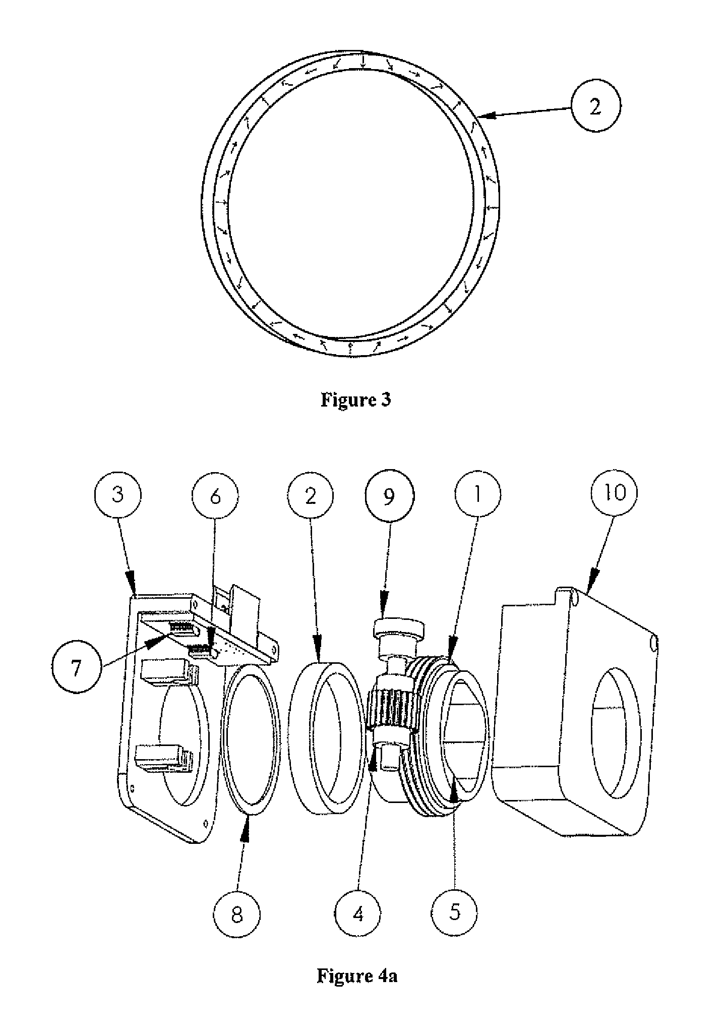
The possible mechanical constructions of the sensor are of the through axis type but nothing prevents the application of the principle in a so-called shaft end configuration.

