Magnetic field generator

a magnetic field and generator technology, applied in the field of magnetic field generators, can solve the problem of performance limitation of superparamagnetic effect, and achieve the effect of improving data storage density and magnetic field strength

Inactive Publication Date: 2013-07-11
UNIV OF SOUTHAMPTON
View PDF8 Cites 17 Cited by
  • Summary
  • Abstract
  • Description
  • Claims
  • Application Information

AI Technical Summary

Benefits of technology

[0024]The magnetic field sources disclosed herein can be used both for longitudinal recording, i.e. with the domains aligned parallel to the surface of the recording medium, and for perpendicular recording, i.e. with the domains aligned perpendicular to the surface of the recording medium. In all cases, the greater magnetic field strength achievable by magnetic field sources disclosed herein will allow improvements in data storage density.

Problems solved by technology

The super-paramagnetic effect is performance limiting.

Method used


Image

  • Magnetic field generator
  • Magnetic field generator
  • Magnetic field generator

Examples


Embodiment Construction

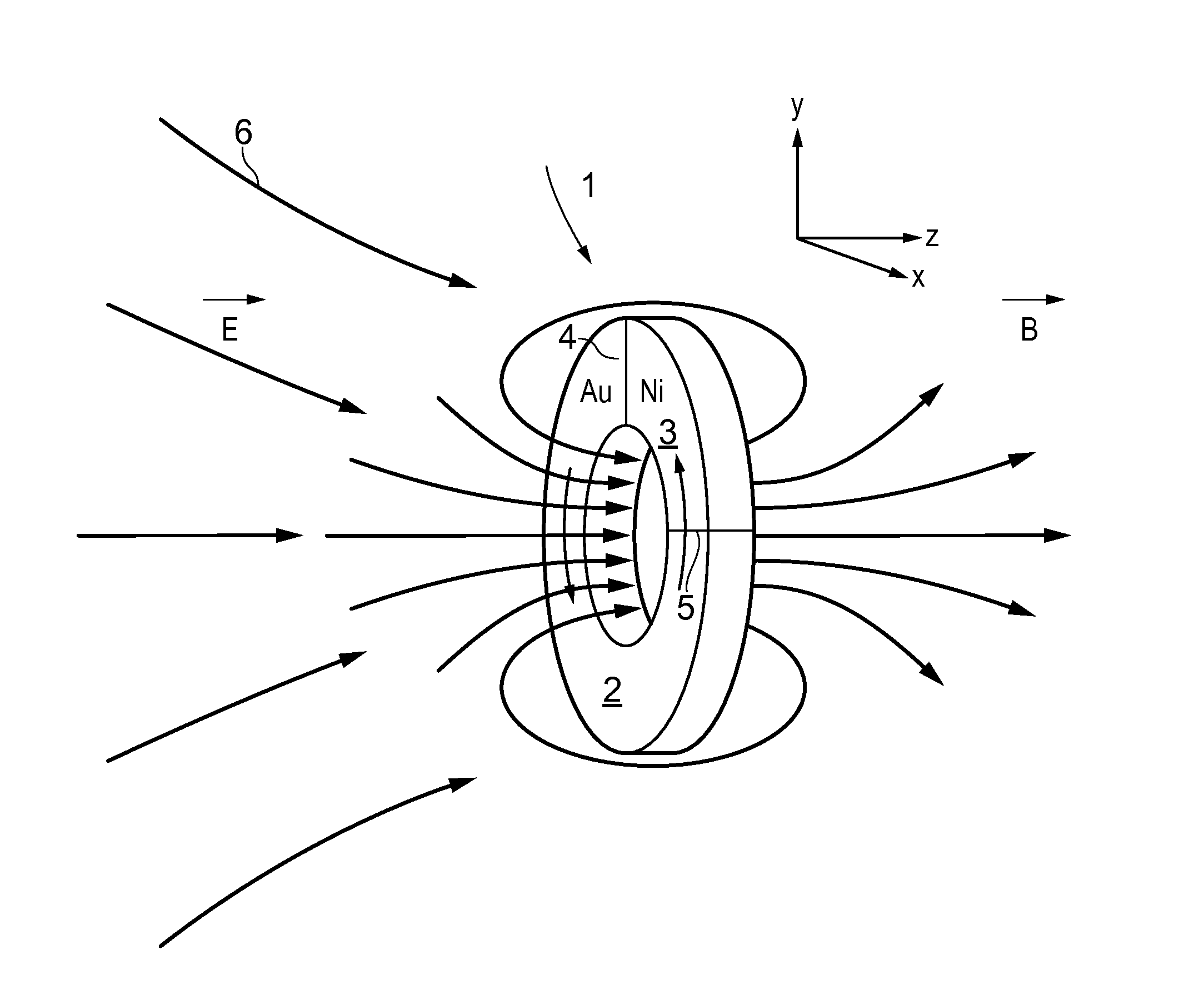
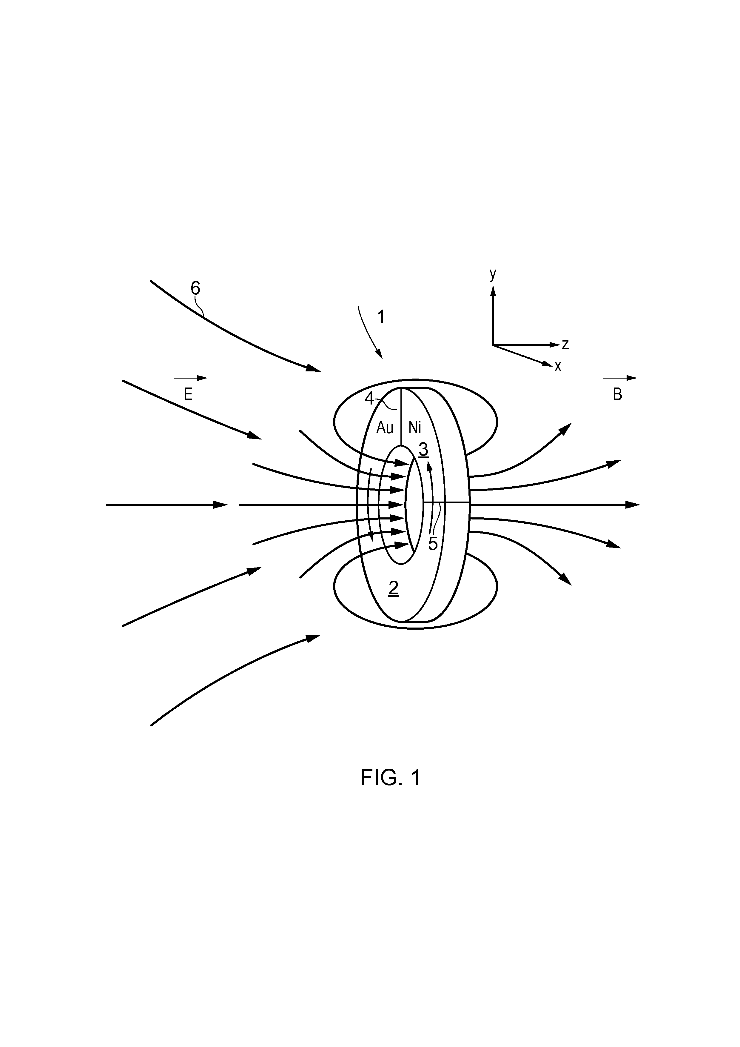
[0045]FIG. 1 is a conceptual representation of a device for generating a magnetic field. The principal active structural element of the magnetic field generator is a conductive ring 1 that forms a closed current path or loop made of materials that support an electron (or hole) plasma. Most metallic materials are suitable, since the electrons in metals generally form a plasma, the associated quasi-particle being referred to as a plasmon. The metallic ring 1 has first and second angular portions 2 and 3 of first and second materials which have first and second Seebeck coefficients which are different. The first and second materials are Au and Ni in the illustrated example. The first and second materials interface at first and second junctions 4 and 5 which are ohmic and are separated angularly in the ring by 90 degrees. The metallic ring is made of a 270° arc of the first material, gold in the example, and 90° arc of the second material, nickel in the example, the ring of the two mate...


PUM

PropertyMeasurementUnit
temperatureaaaaaaaaaa

Abstract

A metallic ring is made of two metals, wherein one metal forms a major arcuate portion and the other a minor arcuate portion of the ring, thereby forming a thermocouple-type structure as a result of the two inter-metallic junctions. The metallic ring supports a surface plasmon whose energy is matched to the energy, i.e. wavelength, of an incident light beam so that the oscillating electromagnetic field of the light resonates with the plasmon. The resonating plasmon causes a temperature difference to arise between the two inter-metallic junctions in the ring. The different Seebeck coefficients of the two metals results in the temperature difference causing a net current to flow around the ring, which in turn generates a magnetic field. Such a thermoelectric metamaterial ring transforms high frequency optical energy into long duration magnetic radiation pulses in the terahertz range. Applications of these devices include high density magnetic recording, magnetic field spectroscopy, and efficient terahertz radiation sources.

Description

[0001]This application claims priority of United Kingdom Patent Application No. 1200186.3 filed Jan. 6, 2012, this application being fully incorporated herewith by reference.BACKGROUND OF THE INVENTION[0002]The invention relates to devices for generating magnetic fields.[0003]Magnetic recording requires relatively high magnetic fields to be produced locally in order to fix the orientation of small magnetic domains on the surface of a magnetic disk. The demand is for ever-increased surface density coupled with stability of the magnetic domains, so once data is written it does not change. These requirements effectively mean that the ideal magnetic material should have high coercivity. However, the higher the coercivity, the greater the magnetic field required to set the domain orientation and hence write a bit of data.[0004]Longitudinal magnetic recording (LMR) is the conventional approach for recording data on magnetic discs. Magnetic domains are aligned with the plane of the magneti...

Claims


Application Information

Patent Timeline
Patent Type & Authority Applications(United States)
IPC IPC(8): H01L31/102G11B13/04
CPCH01L31/102G11B13/04H01L35/20G11B5/127G11B2005/0021G11B5/02H10N10/854
Inventor ZHELUDEV, NIKOLAY IVANOVICHFEDOTOV, VASSILI A.TSIATMAS, ANAGNOSTISDE ABAJO, FRANCISCO JAVIER GARCIASTEWART, WILLIAM JAMES
Owner UNIV OF SOUTHAMPTON
Why Eureka
Try Eureka