Pattern forming process and resist compostion

a pattern forming and composting technology, applied in the field of pattern forming process and resist compostion, can solve the problems of poor quencher function, non-leachable resist material of technology, and several retarded development, and achieve the effect of low lwr and high resolution

Active Publication Date: 2013-07-18
SHIN ETSU CHEM IND CO LTD
View PDF5 Cites 5 Cited by
  • Summary
  • Abstract
  • Description
  • Claims
  • Application Information

AI Technical Summary

Benefits of technology

[0025]Since the sulfonium or iodonium salt of fluoroalkanesulfonamide exerts a satisfactory quencher function, the inventive resist composition comprising the same enables to construct a pattern profile with a high resolution, low LWR, and rectangularity.BRIEF DESCRIPTION OF ACCOMPANYING DRAWINGS
[0026]FIG. 1 is a diagram of 1H-NMR spectrum of the compound obtained in Synthesis

Problems solved by technology

Although lithography using F2 laser (157 nm) was initially thought promising as the next lithography for 45-nm node devices, its development was retarded by several problems.
While the ArF immersion lithography has entered the commercial stage, the technology still needs a resist material which is substantially non-leachable in water.
However, the foregoing carboxylic acids, carboxylic acid ammonium salts, and fluorocarboxylic acid onium salts undergo salt exchange reaction with sulfonic acid at a slow rate, indicating a poor quencher function.

Method used


Image

  • Pattern forming process and resist compostion
  • Pattern forming process and resist compostion
  • Pattern forming process and resist compostion

Examples


synthesis example 1

Synthesis of Triphenylsulfonium Nonafluorobutanesulfonamide (C-1)

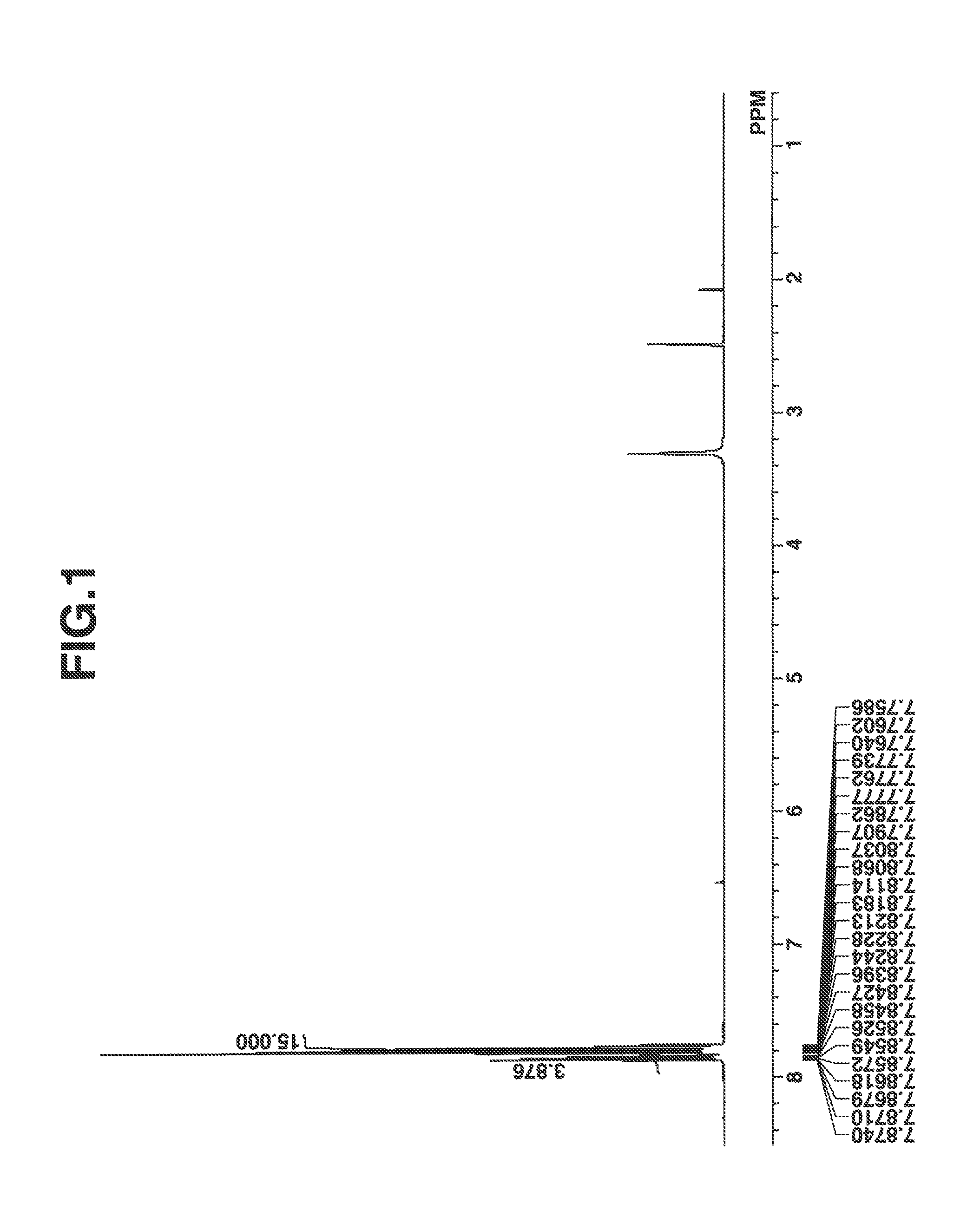
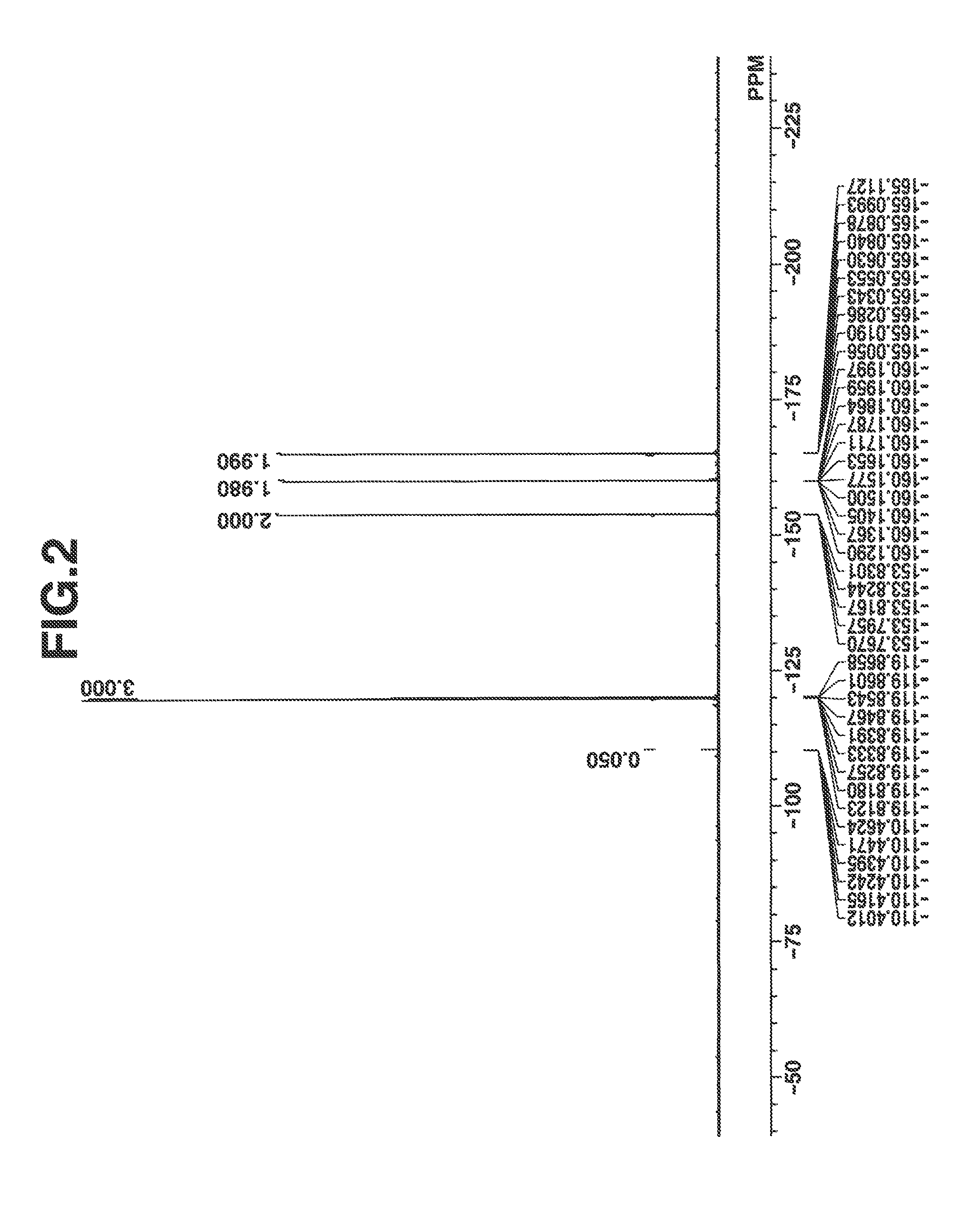
[0138]3.4 g (0.01 mole) of potassium salt of nonafluorobutanesulfonamide, an amount (corresponding to 0.01 mole) of an aqueous solution of triphenylsulfonium methylsulfate and 25 g of dichloromethane were mixed, from which the organic layer was taken out. The organic layer was washed three times with 10 g of water, the solvent was distilled off in vacuum from the organic layer, and diisopropyl ether was added thereto, followed by decantation. The residue was concentrated in vacuum, obtaining 4.7 g of the target compound as oily matter. Yield 85%.

[0139]The compound thus obtained was analyzed by spectroscopy. FIGS. 1 and 2 are nuclear magnetic resonance spectra (1H-NMR and 19F-NMR in DMSO-d6) of the compound. It is noted that a trace of water was observed in 1H-NMR.

Infrared absorption spectroscopy (IR (D-ATR), cm−1):[0140]3062, 1477, 1448, 1350, 1271, 1233, 1191, 1130, 1066, 1033, 1014, 997, 976, 748, 729, 684, 591

Time-o...

examples 1-1 to 1-20

and Comparative Examples 1-1 to 1-11

[0147]A resist solution was prepared by selecting a quencher (in Synthesis Example), a polymer (in Synthesis Example), PAG, amine quencher, and alkali-soluble surfactant (F-1) in accordance with the formulation shown in Table 4, dissolving the components in a solvent, and filtering through a Teflon® filter having a pore size of 0.2 μm. The solvent contained 0.01 wt % of surfactant (F-2).

[0148]The PAG, solvent, amine quencher, alkali-soluble surfactant (F-1) and surfactant (F-2) in Table 4 are identified below.

TABLE 4ResinPAGQuencherSurfactantSolvent 1Solvent 2Resist(pbw)(pbw)(pbw)(pbw)(pbw)(pbw)Example1-1R-01P-1 (80)PAG-1 (6.6)C-1 (6.5)F-1 (5.0)PGMEA (1,728)GBL (192)1-2R-02P-1 (80)PAG-2 (7.6)C-1 (6.5)F-1 (5.0)PGMEA (1,728)GBL (192)1-3R-03P-1 (80)PAG-2 (7.6)C-2 (7.2)F-1 (5.0)PGMEA (1,728)GBL (192)1-4R-04P-1 (80)PAG-2 (7.6)C-3 (8.0)F-1 (5.0)PGMEA (1,728)GBL (192)1-5R-05P-1 (80)PAG-2 (7.6)C-4 (5.9)F-1 (5.0)PGMEA (1,728)GBL (192)1-6R-06P-1 (80)PAG-2 (...


PUM

PropertyMeasurementUnit
feature sizeaaaaaaaaaa
reaction timeaaaaaaaaaa

Abstract

A resist composition is provided comprising a polymer comprising recurring units having a carboxyl group substituted with an acid labile group, an acid generator, a sulfonium or iodonium salt of fluoroalkanesulfonamide and an organic solvent. A positive pattern is formed by applying the resist composition onto a substrate, prebaking to form a resist film, exposing the resist film to high-energy radiation, baking, and immersing in an alkaline developer to dissolve away the exposed region of resist film, but not the unexposed region.

Description

CROSS-REFERENCE TO RELATED APPLICATION[0001]This non-provisional application claims priority under 35 U.S.C. §119(a) on Patent Application No. 2012-004701 filed in Japan on Jan. 13, 2012, the entire contents of which are hereby incorporated by reference.TECHNICAL FIELD[0002]This invention relates to a chemically amplified resist composition comprising a sulfonium or iodonium salt of fluoroalkanesulfonamide, and a pattern forming process using the resist composition.BACKGROUND ART[0003]While a number of recent efforts are being made to achieve a finer pattern rule in the drive for higher integration and operating speeds in LSI devices, DUV and EUV lithography is thought to hold particular promise as the next generation in microfabrication technology. In particular, photolithography using an ArF excimer laser as the light source is thought requisite to the micropatterning technique capable of achieving a feature size of 0.13 μm or less.[0004]The ArF lithography started partial use fro...

Claims


Application Information

Patent Timeline
Patent Type & Authority Applications(United States)
IPC IPC(8): G03F7/004
CPCG03F7/004G03F7/0045G03F7/0046G03F7/0397G03F7/2041Y10S430/12Y10S430/122Y10S430/126G03F7/028
Inventor OHASHI, MASAKIHATAKEYAMA, JUN
Owner SHIN ETSU CHEM IND CO LTD
Why Eureka
Try Eureka