
Device for monitoring intraocular pressure

a technology for intraocular pressure and monitoring devices, applied in the field of monitoring intraocular pressure, can solve the problems of not providing sufficient information for proper management of glaucoma, all pressure measurement devices (contact and non-contact) used to measure iop are affected to different extents, so as to increase accuracy and consistency.

Active Publication Date: 2013-07-18
UNIVERSITY OF DUNDEE +1
View PDF2 Cites 92 Cited by
  • Summary
  • Abstract
  • Description
  • Claims
  • Application Information

AI Technical Summary

Benefits of technology

This patent describes a method for calibrating an apparatus that measures the stiffness of the cornea using a contact lens. The lens has a cavity with thin edges that allows it to deform under pressure from the eyelid. The lens is calibrated using a series of differently curved lenses that the subject wears for a short period of time. The data collected from these lenses is compared to determine the stiffness of the cornea and calibrate the apparatus. The technical effects of this method include improved accuracy in measuring corneal stiffness and improved comfort for the subject wearing the contact lens.

Problems solved by technology

Therefore, measuring IOP only during irregular daytime periods, such as during two or three clinic visits a year, does not provide sufficient information for proper management of the disease.
This also entails that measurements will be taken only during the daytime office hours, which does not capture the natural variation of IOP and its increase during sleep and does not provide sufficient information for proper management of glaucoma.
Other methods of measuring IOP exist which involve non-contact tonometry, but these suffer from the same or other disadvantages.
Furthermore, all pressure measurement devices (contact and non-contact) used to measure IOP are affected to different extents by the stiffness of the cornea.
Thus, for example, a cornea with high stiffness, caused e.g. by high thickness or rigid tissue, would lead to an overestimation of IOP, and could result in a false positive diagnosis of glaucoma.
Due to the requirement to cause applanation of the naturally stiff sclera, these devices are bulky and uncomfortable to wear.

Method used


Image

  • Device for monitoring intraocular pressure
  • Device for monitoring intraocular pressure
  • Device for monitoring intraocular pressure

Examples


example 1

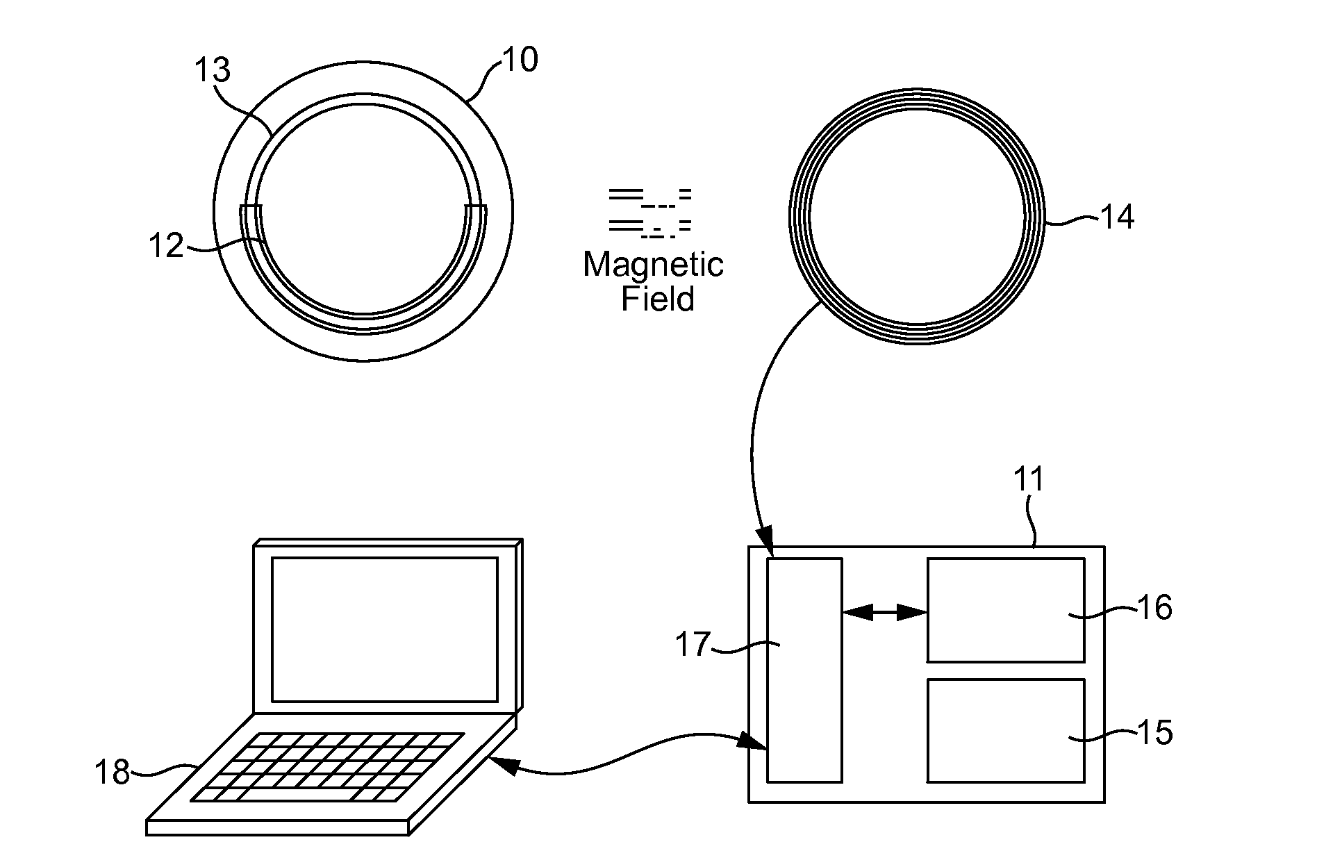
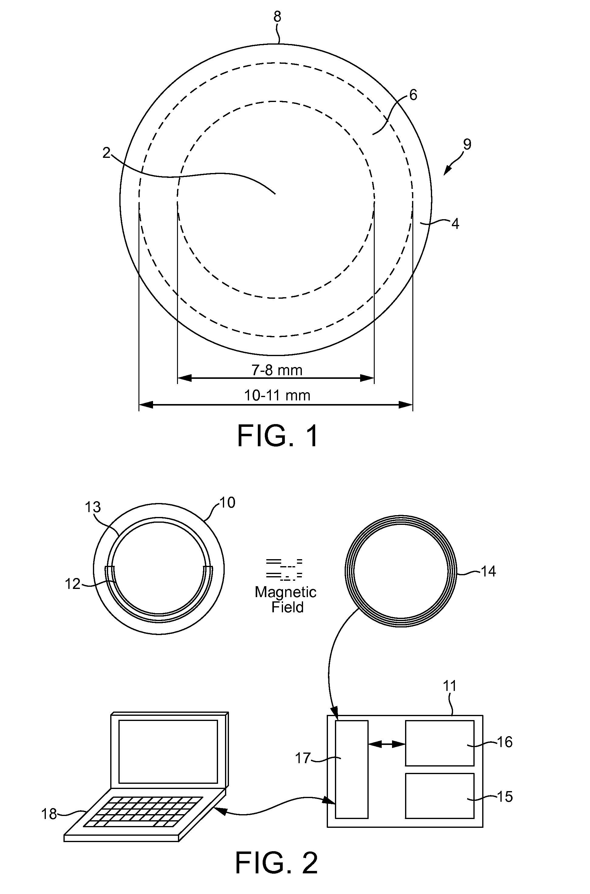
[0105]Referring to FIG. 2, one embodiment of the apparatus of the invention comprises two main components; a soft contact lens 10 and an external instrument 11. While dimensions may vary, in this embodiment the contact lens has a diameter of 14-15 mm and thickness that ranges between 120 μm (along the edge) and 280 μm (at the central region). It is made of soft silicone hydrogel material with Young's modulus, E, of 0.30 MPa and oxygen permeability of over 60×10−11 cm.mLO2 / s.mL.mmHg, to ensure comfort of use over periods over 24 hours, and to enable fitting on corneas with different sizes and curvatures. The central zone with 6.0 mm diameter is free of any obstruction to enable clear vision during use. The lens is be worn in a similar fashion to normal contact lenses on a daily or extended-wear basis.

[0106]The contact lens has a circumferential pressure transducer 12 designed to detect small changes in intraocular pressure (IOP) and transmit them wirelessly to the external instrument...

example 2

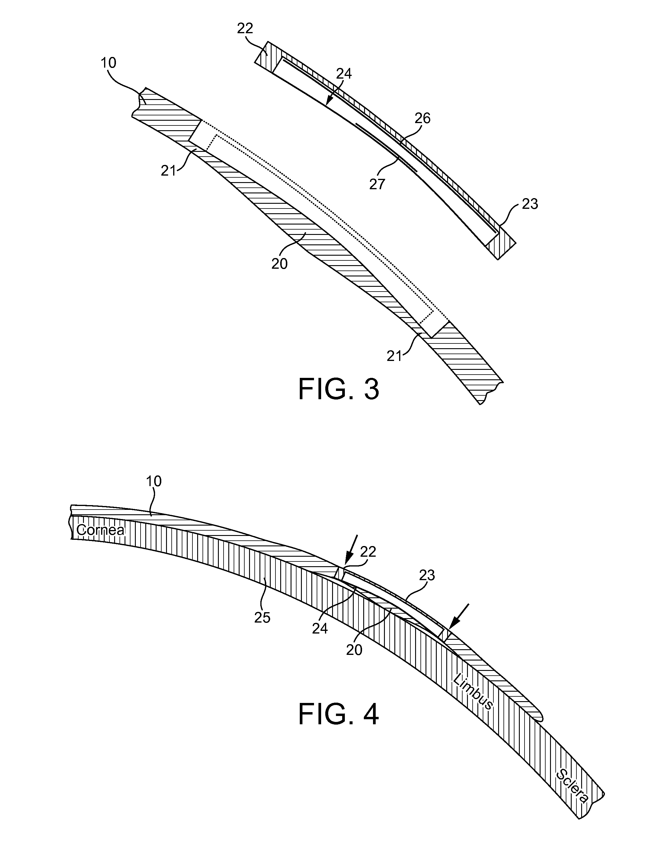
[0108]Referring to FIGS. 3 & 4 details of the pressure sensor design will now be described. This pressure sensor has been found to produce stronger IOP signals, be more reliable and stable in operation in response to eye movement and tear film quality than previous designs. The design is based on indenting the cornea using eyelid pressure and correlating the resulting reactive deformation of the contact lens to the intraocular pressure (IOP). The design involves a modification of a soft contact lens 10 within a zone with typical dimensions of 7 mm internal diameter and 2.5 mm width. The profile in this zone is shaped as shown in FIG. 3, with a protruded part 20 that has weakened (thinner) peripheral regions 21. The space above the protruded part is covered with a relatively stiff bridge 22—formed by a ring of relatively stiff material with an elastic modulus of typically approximately 1 GPa, and a top surface 23 that matches the lens's anterior profile, and provides a smooth continu...

example 3

[0118]Referring now to FIGS. 6a &b, the deformation of the diaphragm 24 is measured using a capacitor system involving two thin metal membranes 26, 27 fixed to the internal surfaces of the bridge member and the diaphragm, respectively. As the diaphragm deforms, the distance between the two metal membranes changes, leading to a change in the capacitance of the capacitor formed by the two membranes. This in turn affects the resonant frequency of the oscillator formed by the combination of the capacitance of the capacitor and the inductance of the responder coil. In order to power the circuit of the capacitor and record the resonant frequency values, a magnetic field is formed between and encompassing a responder coil 28 embedded on the external surface of the bridge member 22 and an exciter coil 29 to be positioned externally close to the eye, e.g. on a pair of spectacles 30 (FIG. 7). By energising the exciter coil with an alternating current, an alternating current will be created in...


PUM


Abstract

Disclosed is a device adapted to measure intraocular pressure comprising: a corneal contact lens having a pressure sensor mounted in a recess or cavity in the contact lens, and wherein the contact lens has a back surface which is formed so as to protrude in a desired portion beyond the profile of the adjacent part of the lens and thus to press against the cornea, which protruding portion experiences a reactive deformation which is detected directly or indirectly by the pressure sensor.

Description

[0001]This invention relates, inter alia, to a contact lens device for the measurement and / or continuous monitoring of intraocular pressure, to apparatus comprising the device, and a method of measuring or monitoring intraocular pressure using the device or apparatus.BACKGROUND[0002]Glaucoma is a group of diseases of the eye which, worldwide, is among the leading causes of irreversible blindness. The major risk predictor for the diseases is increased intraocular pressure (IOP). Therefore, risk profiling for, and management of, glaucoma includes measurements of IOP via tonometry.[0003]It is generally accepted that the normal range of IOP is 10 to 21 mmHg, and individuals with an IOP higher than this range will usually take IOP lowering medication to prevent or delay the progression of glaucoma. Also, IOP for the individual can vary throughout a 24 hour period depending on whether the individual is asleep or awake, the level of physical exertion or hydration, and the psychological sta...

Claims


Application Information

Patent Timeline
IPC IPC(8): A61B3/16
CPCA61B3/16G01L9/12G02C7/04
Inventor ELSHEIKH, AHMEDCLAMP, JOHN
Owner UNIVERSITY OF DUNDEE
Learn More