
Apparatus and method for magnetically conditioning fluids

a technology of magnetic conditioning fluid and apparatus, applied in the direction of magnetic liquid, transportation and packaging, wellbore/well accessories, etc., can solve the problems of substantial problems in the design and implementation of devices and methods for magnetic and electromagnetic fluid treatment, and achieve the effects of improving treatment, limiting corrosion, and improving oil extraction

Inactive Publication Date: 2013-08-01
ENVIRONMENTAL TECH INT
View PDF2 Cites 23 Cited by
  • Summary
  • Abstract
  • Description
  • Claims
  • Application Information

AI Technical Summary

Benefits of technology

The patent text describes methods and devices for conditioning fluids using electromagnet coil designs. These methods and devices can be used to improve the condition of fluids in various ways. The invention can help keep fluids flowing smoothly, prevent corrosion and scaling, reduce microbial contamination, and improve the viscosity and pH of fluids. The invention can also increase the efficiency of pumps and engines, reduce emissions, and improve the quality of water for irrigation. Overall, the invention allows for flexible, controllable, and programmable maintenance of the magnetic field applied to fluids of various kinds.

Problems solved by technology

Yet, substantial problems remain in the design and implementation of devices and methods for magnetic and electromagnetic fluid treatment.

Method used


Image

  • Apparatus and method for magnetically conditioning fluids
  • Apparatus and method for magnetically conditioning fluids
  • Apparatus and method for magnetically conditioning fluids

Examples


Embodiment Construction

[0024]The invention will now be described more fully hereinafter with reference to the accompanying drawings, in which some, but not all concepts of the invention are illustrated. Indeed, the invention may be embodied in many different forms and should not be construed as limited to the examples set forth herein; rather, the embodiments provided in this disclosure are intended to satisfy applicable legal requirements.

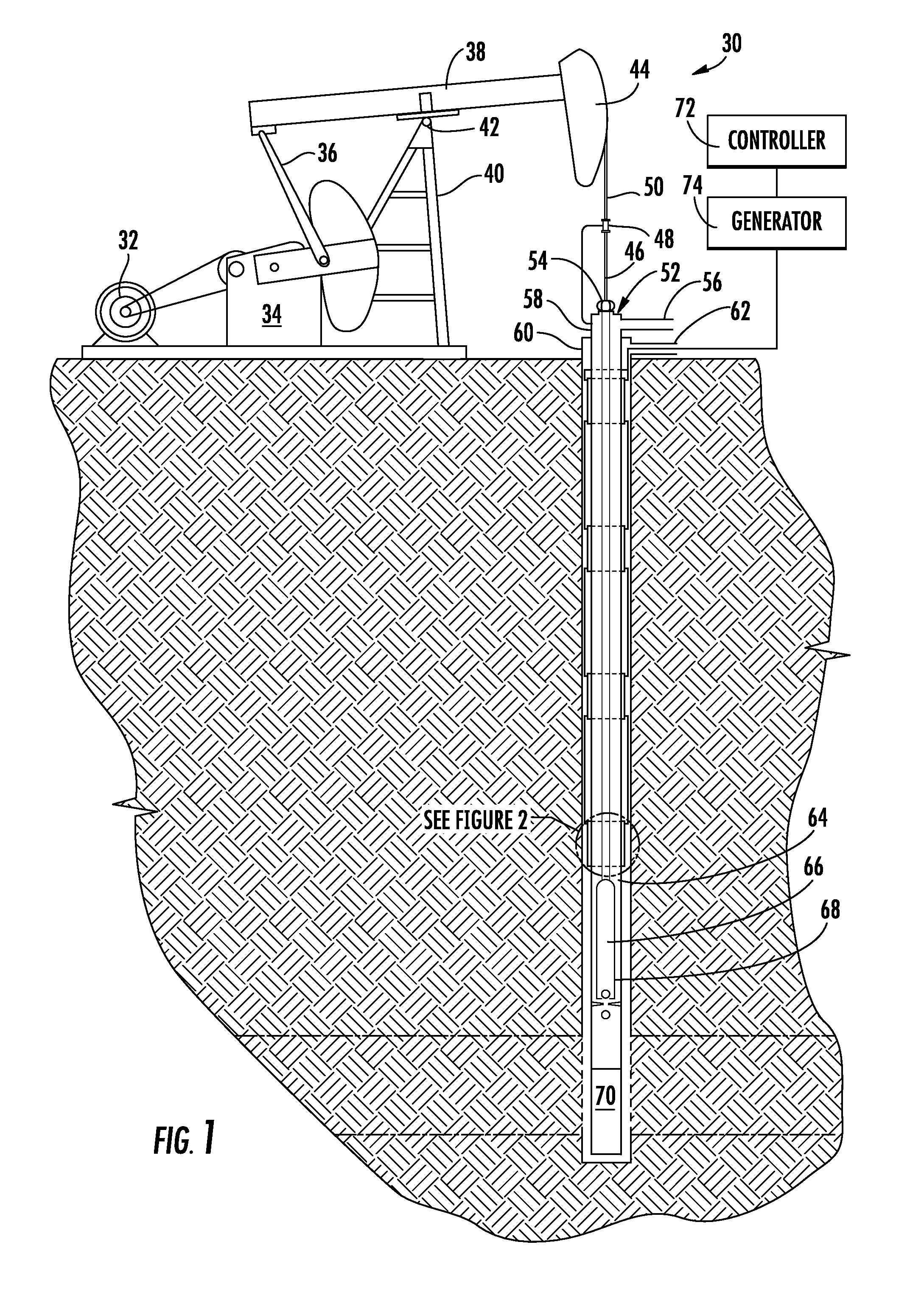
[0025]FIG. 1 illustrates generally at 30 a sucker-rod pumping system having a motor 32 acting as a prime mover and generating rotational motion. Above ground components include a motor 32, which may be powered by electricity, diesel fuel, natural gas, propane, or gasoline or any other source of power. A gear reducer 34 reduces the speed of rotation and provides the torque necessary to drive the sucker-rod pumping system. The gear reducer connects a counterbalanced crank arm 36 to a walking beam 38 mounted on Samson posts 40. The walking beam pivots up and down about sad...


PUM


Abstract

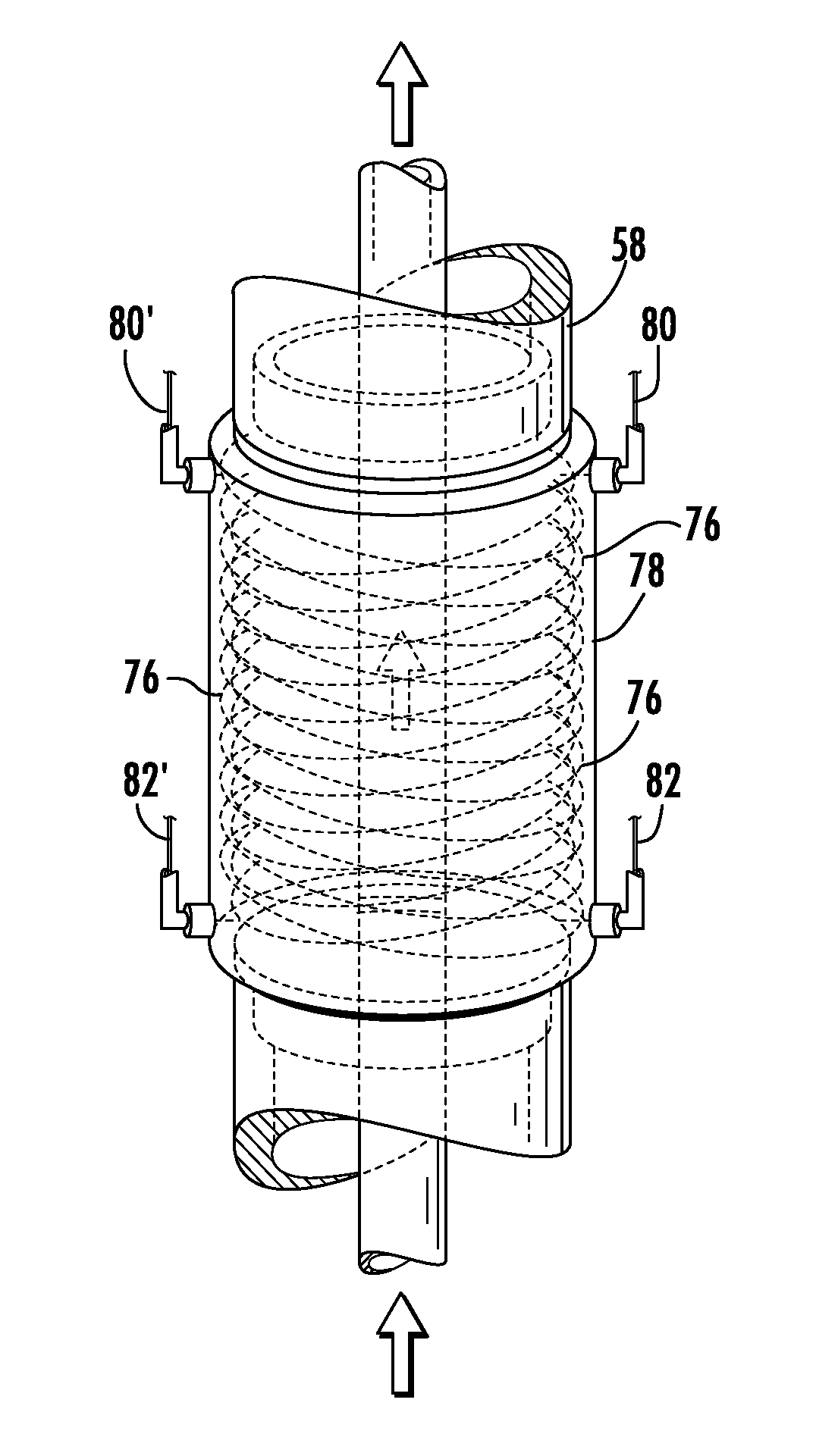
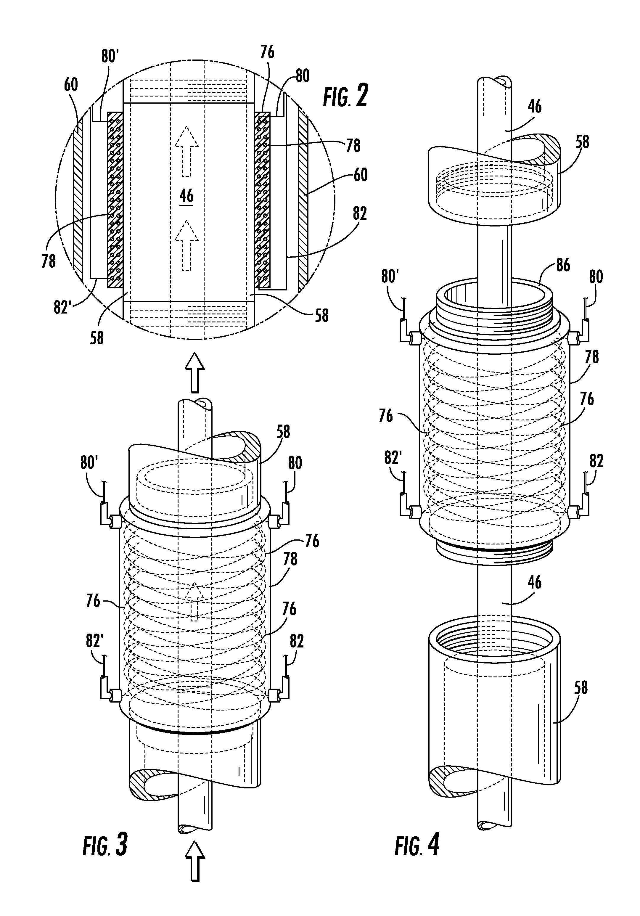
Methods and apparatus for fluid conditioning to reduce scaling, inactivate microbes, reduce surface tension, maintain fluid composition, and improve pumping are provided for use in treating crude petroleum, industrial water, agricultural water, municipal water supplies, or any fluid flow system and comprise electromagnets of variable control that can be powered or in which a current can be induced by a permanent magnet. Magnetic field direction and intensity can be selected depending on the nature of the fluid and in some embodiments, the field can be varied during operation, including pulsing and variably selecting one or more field directions and intensities, or combinations thereof, during operation. A non-magnetic fluid transfer conduit section has at least one conductor assembly mounted about the section. In one embodiment, the conductor assembly comprises a concentric, tilted double helix coil or multipole coil. If desired, one or more rotating or reciprocating permanent magnets may be located in magnetic field contact with one or more multipole conductor assemblies and rotated or reciprocated to induce a current in the multipole conductor assembly, thereby to induce a magnetic field in the conductor assembly.

Description

FIELD OF THE INVENTION[0001]The invention relates to apparatus and methods for treating flowing fluids in a magnetic field, and particularly to improving one or more characteristics of a fluid or gas or fluid and gas mixture by subjecting the fluid to a magnetic field.BACKGROUND OF THE INVENTION[0002]Numerous references describe the use of magnets of various types in connection with treating fluids and for a variety of purposes. For example, U.S. Pat. No. 5,465,789 describes using the reciprocating motion of permanent magnets mounted on the central rod of a wellbore in a subterranean formation to energize stationary electrical coils located beneath the pump. The magnetic flux resulting from the up-and-down movement of the rod is said to extend into the surrounding reservoir formation and to attract magnetically conductive particles to the wellbore. The magnetic particles are said to promote hydrocarbons in the formation migrating to the well bore, thereby increasing production. U.S....

Claims


Application Information

Patent Timeline
IPC IPC(8): F16L55/00
CPCF16L55/00C02F1/485E21B41/0085E21B43/2401H01F5/00C02F2209/003C02F2303/22H01F1/44C02F2201/483E21B37/00Y10T137/206Y10T137/0391
Inventor FREESE, MATTHEW J.
Owner ENVIRONMENTAL TECH INT
Learn More