Waste solid cleaning

a technology of solid cleaning and oil, applied in the direction of contaminated soil reclamation, mixing methods, separation processes, etc., can solve the problems of oil-contaminated drill cuttings' disposal, environmental pollution, and its own environmental problems, and achieve the effect of improving the extraction of oil

Inactive Publication Date: 2007-03-15
MARTIN ANDREW JOHN
View PDF9 Cites 17 Cited by
  • Summary
  • Abstract
  • Description
  • Claims
  • Application Information

AI Technical Summary

Benefits of technology

[0045] A specific property relevant to the microemulsions of the present invention is that the interfacial surface tension generated between a microemulsion phase and a polar phase (e.g. water, air or a solid material such as clay) is extremely low. Sodium chloride may also be added to thermodynamically force the oil out of the water whereupon the oil may be skimmed from the top of the water. Although not wishing to be bound by theory it is thought that on formation of the microemulsion, the interfacial surface tension between an upper oil-containing microemulsion phase and a lower water phase is extremely low allowing complete separation of the two phases.
[0046] Typically, any microemulsion forming surfactant which is capable of effectively trapping oil within a surfactant shell is suitable for the present invention. The surfactant may also be mixed with a salt such as sodium chloride which may improve the extraction of the oil. Mixtures of different surfactants may also be used.

Problems solved by technology

Disposal of oil-contaminated drill cuttings is a major problem in the oil industry.
Although it was previous practice to dispose of untreated cuttings simply by dumping the cuttings adjacent the drill site, for example, onto the seabed, this is environmentally unfriendly and is now illegal in many jurisdictions.
However, this again has its own environmental problems.
With thousands of tonnes of drill cuttings being formed in drilling operations worldwide, the transportation costs are significant.
The storing of oil-contaminated drill cuttings and well bore clean-up fluids on a drilling platform is a major problem due to limited storage space.
Many containers or skips are therefore required which takes up valuable deck space.
Furthermore, if bad weather prevents transport vessels from emptying the full containers or skips, drilling operations may have to be suspended until the weather improves and the material can be transported.
The current practice of storing oil-contaminated drill cuttings in containers or skips on the oil platform also leads to health and safety issues.
This is a slow process and requires many crane movements (up to 1,000 additional movements for every well), thereby increasing the risk of accidents occurring.
However, such slurified cuttings are generally too fine to be handled easily in conventional onshore drill cutting processing facilities.
Such a process also has the disadvantage of increasing the volume of the waste.
Similarly, in other industries such as refining and waste management, there are large quantities of oily solids, such as interceptor sludges and the like that require disposal.
Landfill is no longer an alternative for liquid wastes, due to new landfill legislation, and as a result these substances require treatment to provide recyclable / inert materials than can be disposed of in an environmentally safe manner.
This is expensive from both a financial and an environmental aspect.
The material obtained using these processes may not have a low enough oil content to be disposed of overboard on an oil platform and may have to undergo a series of treatment cycles or more than likely still require transportation to an onshore treatment facility.
In addition, the sample sizes used in these patents is only about 60 g and is therefore not a realistic measure for treating large scale volumes.
A further significant problem is the actual percentage of oil content discussed in the prior art such as in GB 2347682B.
Retort methods are inherently inaccurate and produce an error of at least plus / minus 2.5% in measured oil content.
Additionally, in GB 2347682B a polycarbonate centrifuge bottle is used which may further distort the results as the polycarbonate will potentially absorb some oil.
The method disclosed in GB 2347682B is therefore highly unlikely to produce repeatable results when treating drill cuttings or oil slops to provide resulting solid material which has an oil content of less than 1%.
The oil content must also be measured using accurate measurement devices such as Gas Chromatography (GC) or Fourier Transform Infrared Spectroscopy (FTIR) otherwise anomalous results are obtained.

Method used


Image

  • Waste solid cleaning
  • Waste solid cleaning
  • Waste solid cleaning

Examples


example 1

[0147] Oil based mud slops (hereinafter referred to as raw slops) were obtained as a result of pit cleaning activities on a mobile offshore installation in the North Sea. The raw slops contain low toxicity mineral base oil, water barites and sand / silt contaminants—1.915SG (i.e. specific gravity) and 28.61% oil by weight.

[0148] The process of treating the raw slops is set out below.

Step 1

[0149] 1. Sample A—raw slops. 250 litres of raw slops were processed resulting in 25 litres of oily solids comprising 16.11% oil by weight and 225 litres of liquid extract comprising 12.5% oil by weight.

Step 2

[0150] 1. 2.5 litres of a 10% surfactant solution and 25 litres of salt water was added to 25 litres of the oily solids obtained in Step 1. The surfactant is a proprietary product—SP107, available from Surface Technologies Solutions Ltd, Watermark House, Heriot-Watt Research Park, Avenue North, Edinburgh EH14 4AP. This was thoroughly mixed at 20° C. for about 10 minutes.

[0151] 2. On sepa...

example 2

[0161] The object of this Example was to try different experimental conditions and see how differences in mixing and reducing the particle sizes affected the % of oil in the material.

[0162] In all of the results below in Examples 2A-2F, a batch of oil-contaminated material of 0.5 m3 was used which had a weight of 0.8 tonnes. Additionally, the same surfactant of SP107 (Trade Name) from SAS Ltd. as used in Example 1 was used with a concentration of 7.5%.

[0163] The % of oil on solids in each of the Experiments below was measured using gas chromatography (GC). Gas chromatography (GC) is a highly accurate method in which to measure the % of oil in the material. This is in contrast to previously used retort methods.

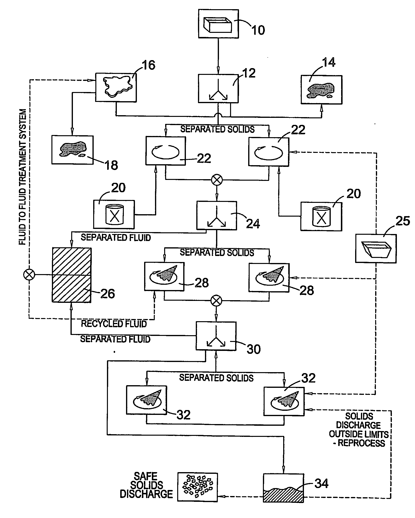
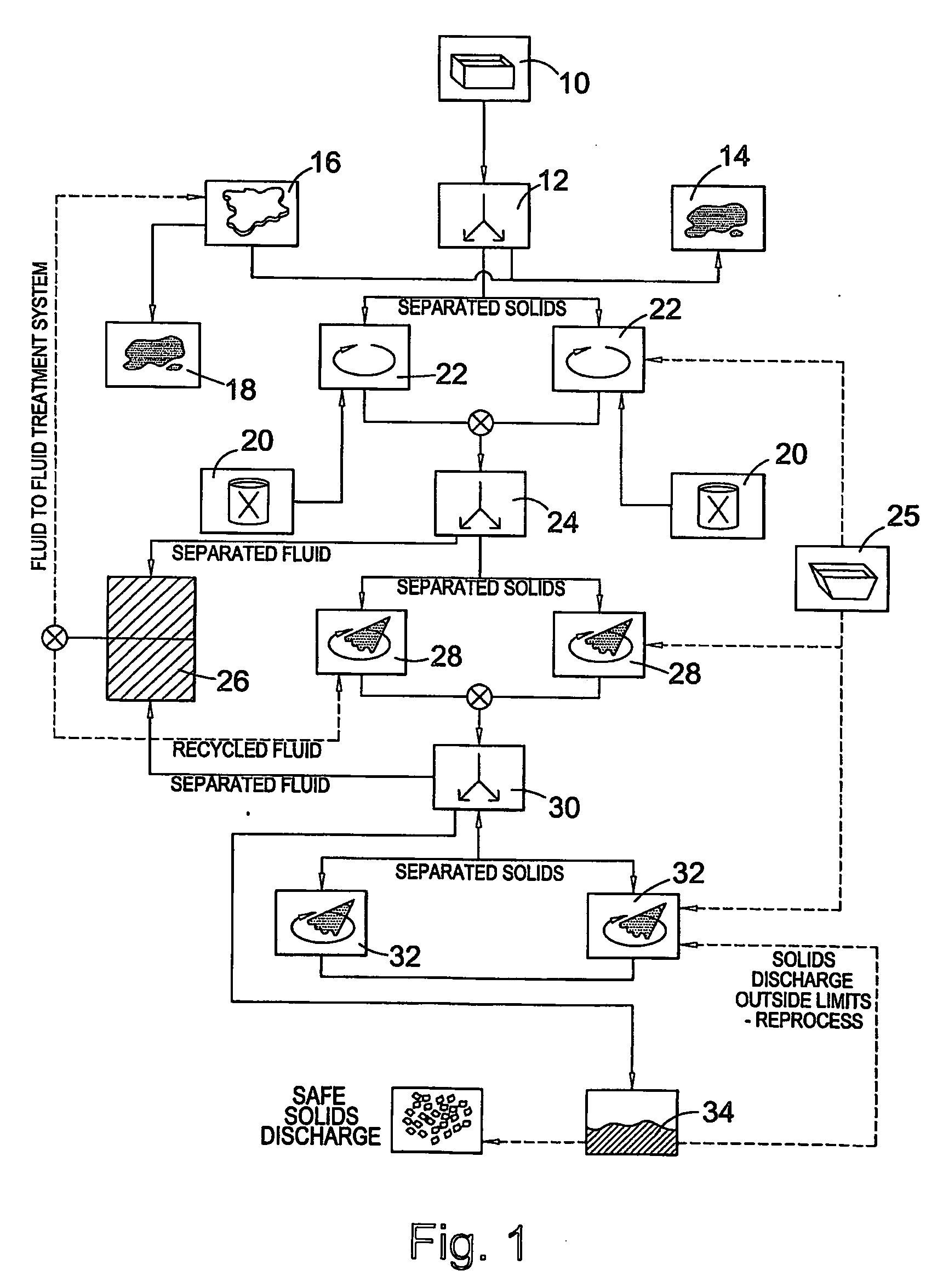
[0164] Furthermore, the same flow process as clearly illustrated in FIGS. 13 to 16 remain unchanged in each of the Experiments detailed below.

example 2a

[0165] In a first experiment, raw slops were used.

[0166]FIGS. 13 and 14 clearly explain the process as shown in FIG. 1 specifically for raw slops.

[0167] In this experiment, the raw slops are subjected to an electrostatic pulse burst system in an attempt to break the oil in water emulsion prior to mixing.

[0168] The raw slops were then mixed in an air driven STEMDRIVE (Trade Name) fluidic mixer for 10 minutes. A significant amount of foaming was found to occur with a resulting “RAG” (i.e. scum layer) being formed. It was difficult to recover oil from this “RAG” layer.

[0169] As illustrated in FIG. 14, the slops were then subjected to two rinsing steps.

[0170] At each stage of the process, the % of oil on solids was measured using gas chromatography (GC). These results are shown below in Table 2.

TABLE 2TotalTotalTotalHydrocarbonsTotalHydrocarbonsHydro-(g / kgHydrocarbons(g / kgcarbonssample)percentsample)percentDRYDRYWETWETRaw573.457.34159.4015.94SlopsSolids94.99.4969.646.96Post MixSo...


PUM

PropertyMeasurementUnit
particle sizeaaaaaaaaaa

Abstract

This invention relates to a method and apparatus for removing oil from oil-contaminated waste. In particular, the present invention relates to the removal of oil from drilling wastes such as drill cuttings and oil slops, and other industrial oily wastes such as refinery and interceptor wastes by forming a microemulsion of reduced particle size oil-contaminated material.

Description

FIELD OF THE INVENTION [0001] This invention relates to a method and apparatus for removing oil from oil-contaminated waste. In particular, the present invention relates to the removal of oil from drilling wastes such as drill cuttings and oil slops, and other industrial oily wastes such as refinery and interceptor wastes by forming a microemulsion of reduced particle size oil-contaminated material. BACKGROUND OF THE INVENTION [0002] Drilling fluids or “muds” are oil- or water-based formulations which are used as lubricants and stabilisers in the drilling of oil and gas wells. Oil-based muds tend to have superior performance and are used in difficult drilling conditions, such as in horizontal drilling. [0003] Drilling mud is pumped down hole to a drill bit and provides lubrication to the drill string and the drilling bit. The mud also prevents or inhibits corrosion and can be used to control the flow of fluid from a producing formation. [0004] Drilling mud returning to surface may c...

Claims


Application Information

Patent Timeline
Patent Type & Authority Applications(United States)
IPC IPC(8): B08B7/00B01F23/00B03B9/02B09C1/02E21B21/06
CPCB03B9/02E21B21/063B09C1/02B01D12/00E21B21/06B01F23/00
Inventor MARTIN, ANDREW JOHN
Owner MARTIN ANDREW JOHN
Why Eureka
Try Eureka