
Plasma sterilizer, plasma sterilization system, and plasma sterilization method

a sterilizer and plasma technology, applied in the field of sterilization apparatus, can solve the problems of difficult application of the sterilization methods mentioned above in a bcr, inability to use heat sterilization methods which raise the temperature to about 120° c., and process time problems, and achieve the effect of high efficiency sterilization upon sterilization process

Inactive Publication Date: 2013-08-08
HITACHI LTD
View PDF2 Cites 7 Cited by
  • Summary
  • Abstract
  • Description
  • Claims
  • Application Information

AI Technical Summary

Benefits of technology

The present invention is about a new plasma sterilizer that can efficiently kill harmful organisms. The invention includes different configurations of the sterilizer and a method to detect the target processing organism. The technical effect of the invention is to provide a more effective and efficient way to sterilize surfaces and equipment, reducing the risk of cross-contamination and improving safety in various industries such as healthcare, food processing, and electronics.

Problems solved by technology

BCR, in which aseptic manipulation can be carried out, is essential in clinical studies and thus establishment of sterilization techniques for surface adhesive bacteria has been an important problem to maintain the indoor environment in the BCR.
Although there are various sterilization methods depending on material, shape, etc. of the sterilized subject as exemplified above, application of the sterilization methods mentioned above in a BCR is considered to be difficult.
For example, since the floor in a BCR is a resin-based material, the heat sterilization methods which raise temperature to about 120° C. cannot be used.
Also, the process time is a problem in the radiation sterilization methods because its sterilization ability is low and thus radiation for several tens of minutes to several hours is required.

Method used


Image

  • Plasma sterilizer, plasma sterilization system, and plasma sterilization method
  • Plasma sterilizer, plasma sterilization system, and plasma sterilization method
  • Plasma sterilizer, plasma sterilization system, and plasma sterilization method

Examples


first embodiment

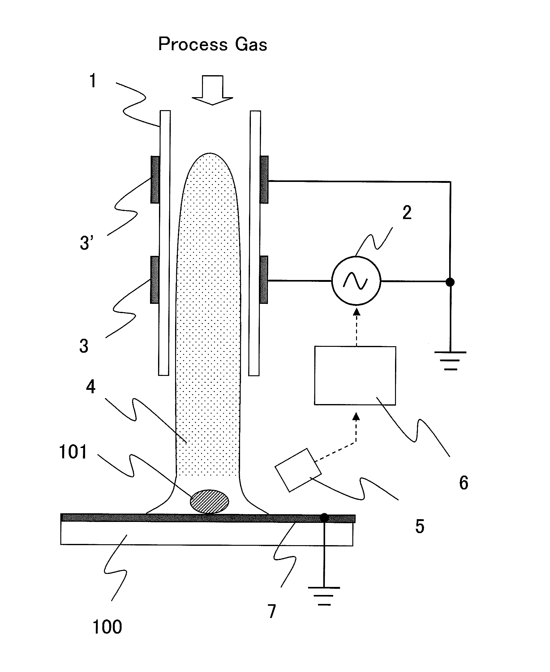
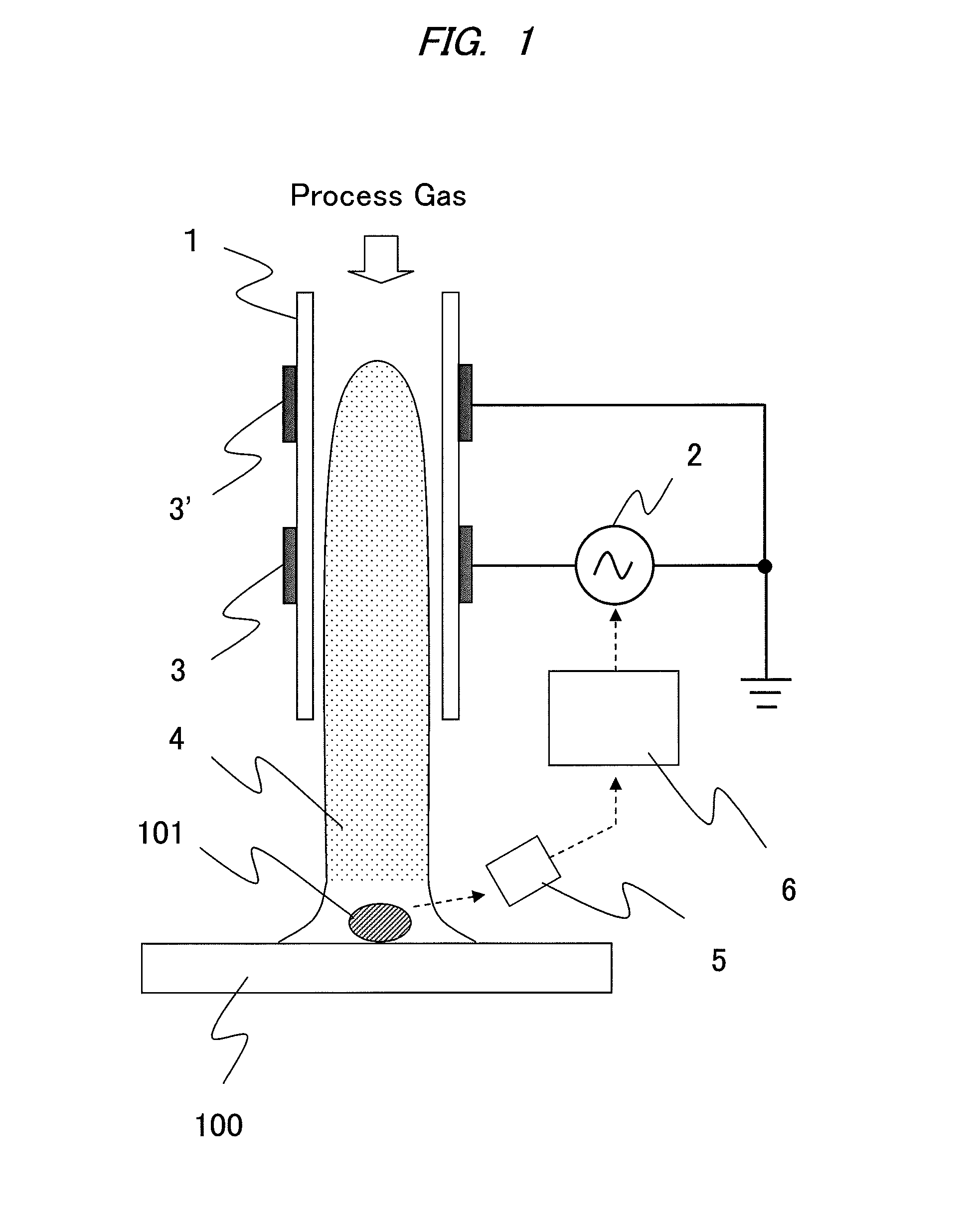
[0038]FIG. 1 is a schematic diagram illustrating a configuration of a plasma sterilizer according to the present invention. Under the atmospheric pressure, there is a plasma source to which a process gas is supplied. In the plasma source, a high-frequency electrode 3 to which power is applied from a high-frequency power supply 2 and a ground electrode 3′ are provided and the plasma source generates plasma 4 inside a tube of an insulator 1 to irradiate plasma to a processing target organism 101 that is on a processing target surface 100.

[0039]Incidentally, the irradiation of the plasma as referred to herein is gas generated upon discharge and it is directed to a state in which freely moving charged particles are present and electrically neutral. That is, phenomena not only the discharging portion directly works on bacteria but also radicals generated by the discharge gives a sterilization effect on bacteria are included. Thus, the sterilization process can be performed when a generat...

second embodiment

[0066]A second embodiment of the present invention will be described hereinafter. Even when other plasma generating methods than that of the first embodiment is used, determination of presence and inactiveness of a target processing organism 101 by light emission spectrum of the present invention is possible.

[0067]For example, FIG. 3 is a schematic diagram illustrating another example of the configuration of the plasma sterilization apparatus of the present invention. In the structure, a high-frequency electrode 3 and a ground electrode 3′ are facing each other and at least one of the electrodes is protected by an insulator 1. Plasma 4 is generated at a portion where a space between the facing electrodes is the narrowest and irradiated onto the target processing organic 101 that is on a target processing surface 100 along a flow of a process gas.

[0068]A spectrometer 5 and a control board 6 are installed in the same manner as the first embodiment and an output of a high-frequency pow...

third embodiment

[0072]A third embodiment of the present invention will be described hereinafter.

[0073]FIG. 5 is a schematic diagram illustrating a plasma sterilization apparatus and a configuration of a target processing surface of the present invention. By providing a ground electrode for target processing surface 7 to a topmost surface of a target processing surface 100, an electric field is formed between a high-frequency electrode 4 and the ground electrode for target processing surface 7. In this manner, plasma is accelerated in the electric field and collide with the target processing organism 101 and thus hydrogen desorption of the target processing organism by oxygen radicals is accelerated.

[0074]As a result, hydrogen radicals generated per a unit time are increased and light emission detection of hydrogen is made easier. Also, required time of inactivation can be also shortened.


PUM


Abstract

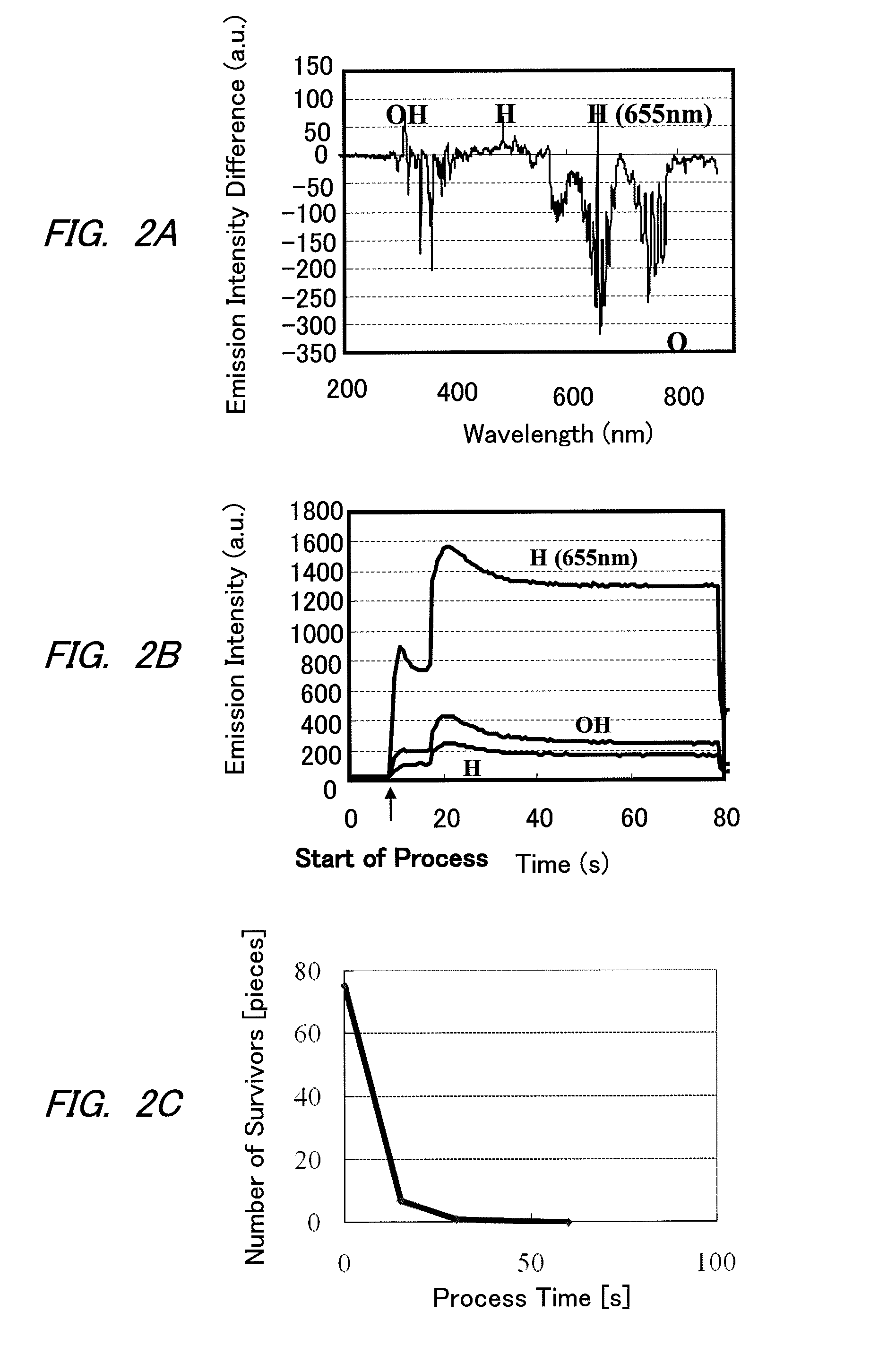
An apparatus which determines activeness / inactiveness of bacteria in real time by measuring a specific light emission spectrum upon performing sterilization using plasma to highly efficiently sterilize is provided. As solving means, plasma is irradiated on a processing target from a plasma source connected to an alternate-current power supply and light emission of the processing target caused by the irradiation of plasma is detected by a light emission intensity detector unit. Particularly, by detecting wavelength intensity of hydrogen or hydroxyl group, activeness / inactiveness of bacteria can be determined at an early stage. Thus, an appropriate output of a power supply for sterilization can be controlled.

Description

TECHNICAL FIELD[0001]The present invention relates to a plasma sterilization apparatus which inactivates adhesive bacteria and floating (airborne) bacteria in facilities and space such as bioclean rooms (herein after, referred to as BCR) requiring removal of microorganisms; more particularly, the present invention relates to monitoring technology capable of detecting activeness or inactiveness of bacteria in real time.BACKGROUND ART[0002]Expectations have been raised for achieving regenerative medicine using artificially cultured cells and tissues to regenerate damaged skin, cornea, internal organs, etc. for functional recovery of patients. The number of patients having target diseases is expected to be 20,000 per year even when only those having cornea regeneration are considered and thus practical application of technology has been longed for. It is expected that participation of pharmaceutical companies will also become obvious in the future and regenerative medicine will grow in...

Claims


Application Information

Patent Timeline
IPC IPC(8): A61L2/20
CPCA61L2/14H05H1/2406H05H2001/2443G01N21/67H05H2245/1225A61L2/20H05H2001/2462H05H1/2465H05H1/2443H05H2245/36
Inventor TANDOU, TAKUMINEGISHI, NOBUYUKIITABASHI, NAOSHI
Owner HITACHI LTD
Learn More