Circuit and method for improving noise immunity of a single-end level shifter in a floating gate driver

a single-end level shifter and floating gate technology, applied in the field of floating gate drivers, can solve the problems of low noise immunity of single-end level shifters and significant cross-talk issues, and achieve the effect of improving the noise immunity of single-end level shifters and reducing the area penalty

Active Publication Date: 2013-08-15
RICHTEK TECH
View PDF6 Cites 12 Cited by
  • Summary
  • Abstract
  • Description
  • Claims
  • Application Information

AI Technical Summary

Benefits of technology

[0011]The present invention not only has the lower area penalty of a single-end level shifter, but also improves noise immunity of the single-end level shifter.

Problems solved by technology

The input transistors M1 and M2 require large area if formed outside the ultra-high-voltage floating well 12, and may cause significant cross talk issue if formed in the ultra-high-voltage floating well 12, as a result of their proximity to each other.
Nevertheless, the single-end level shifter is disadvantaged by low noise immunity.
Since the single-end level shifter outputs the translated set signal Set and the translated reset signal Reset through the common output terminal AA, the aforesaid noise may lead to erroneous action of the D flip-flop or even cause the power transistors T1 and T2 to be turned on at a same time.

Method used


Image

  • Circuit and method for improving noise immunity of a single-end level shifter in a floating gate driver
  • Circuit and method for improving noise immunity of a single-end level shifter in a floating gate driver
  • Circuit and method for improving noise immunity of a single-end level shifter in a floating gate driver

Examples


first embodiment

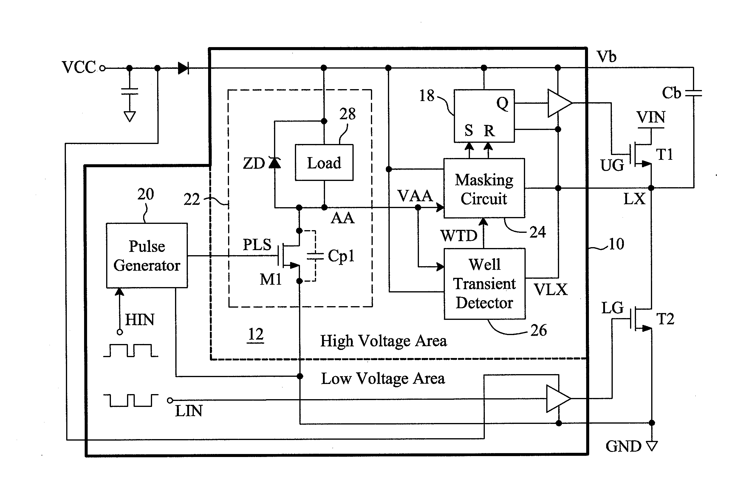
[0022]FIG. 3 is a circuit diagram of a first embodiment for the well transient detector 26 shown in FIG. 2, which is designed to detect noise generated when the voltage VLX drops down. In this embodiment, a transistor M3 and a current source 30 are connected in series between the common output terminal AA of the single-end level shifter 22 and the ultra-high-voltage floating well 12, the control terminal, i.e., the gate, of the transistor M3 is connected to the power input terminal Vb, and a buffer 32 has two bias input terminals connected to the power input terminal Vb and the ultra-high-voltage floating well 12, respectively, and determines the well transient detect signal WTD according to the signal at its signal input terminal, i.e., the drain voltage Sf of the transistor M3. In stable states, the transistor M3 is turned off and thus the voltage Sf is approximately equal to VLX and the output WTD of the buffer 32 is logic 0. When the voltage VLX suddenly fall below a threshold v...

second embodiment

[0023]FIG. 4 is a circuit diagram of a second embodiment for the well transient detector 26 shown in FIG. 2, which is designed to detect noise generated when the voltage VLX rises. In this embodiment, a Zener diode ZD1 and a current source 30 are connected in series between the power input terminal Vb and the ultra-high-voltage floating well 12, a current source 34 and a transistor M3 are connected in series between the power input terminal Vb and the common output terminal AA of the single-end level shifter 22, and a buffer 32 has two bias input terminals connected to the power input terminal Vb and the ultra-high-voltage floating well 12, and determines the inverted signal WTD , which is out of phase with the well transient detect signal WTD, according to the signal at its signal input terminal, i.e., the drain voltage Sf of the transistor M3. In stable states, the transistor M3 is turned off and thus the voltage Sf is approximately equal to Vb and the output WTD of the buffer 32 ...


PUM


Abstract

A floating gate driver uses a single-end level shifter to translate a set signal and a reset signal induced by a rising edge and a falling edge of a switch signal to a common output terminal to generate an output voltage for a bistable circuit to generate a level shifted switch signal. Under control of a well transient detect signal asserted by detecting noise in the output voltage, a masking circuit between the single-end level shifter and the bistable circuit masks noise in the output voltage. This configuration has lower area penalty and better noise immunity.

Description

FIELD OF THE INVENTION[0001]The present invention is related generally to a floating gate driver and, more particularly, to a circuit and a method for improving noise immunity of a single-end level shifter in a floating gate driver.BACKGROUND OF THE INVENTION[0002]The high voltage integrated circuit (HVIC) is necessary for high voltage applications, such as motor, ballast, two inductor one capacitor (LW), and cold cathode fluorescent lamp (CCFL). For example, referring to FIG. 1, a high-side power transistor T1 and a low-side power transistor T2 of a half H-bridge circuit are controlled by gate control signals UG and LG provided by a controller IC 10, respectively. The gate control signals UG and LG are generated responsive to non-overlapping switch signals HIN and LIN, respectively. The direct-current (DC) input voltage VIN for the half H-bridge circuit may be up to 300-600 V or higher. In order to reduce the number of high-voltage circuit components used in the controller IC 10 an...

Claims


Application Information

Patent Timeline
Patent Type & Authority Applications(United States)
IPC IPC(8): H03K3/013
CPCH03K19/00361H03L5/00H03K3/013H03K19/018507
Inventor TSENG, PEI-KAITANG, CHIEN-FUCHEN, ISAAC Y.
Owner RICHTEK TECH
Why Eureka
Try Eureka