Interference filter, optical module, and electronic apparatus

a technology of optical modules and filters, applied in the direction of optical radiation measurement, instruments, spectrometry/spectrophotometry/monochromators, etc., can solve the problems of low long-term reliability of silver, easy sulfurization, low heat resistance of silver, etc., and achieve high reliability

Active Publication Date: 2013-08-22
SEIKO EPSON CORP
View PDF13 Cites 9 Cited by
  • Summary
  • Abstract
  • Description
  • Claims
  • Application Information

AI Technical Summary

Benefits of technology

[0015]An advantage of some aspects of the invention is to prevent a metal film as an optical film from being deteriorated by oxidation, sulfurization, and so on, and further to prevent electrification of the surface of the optical film.
[0018]According to this application example, by covering the surface and the end portion of the metal film with the barrier film, it becomes possible to block a gas and so on to be the causes of degradation of the reflectance of the metal film such as oxygen, water, or sulfur. Therefore, deterioration of characteristics of the optical film can be prevented.
[0024]Further, by using a film made of one or a plurality of substances selected from a group consisting of indium-based oxides, tin-based oxides, and zinc-based oxides, or a layered film composed of films each including a substance selected from the group as the barrier film, there is an advantage of preventing the entry of the gasses causing oxidation or sulfuration of the optical film made of Ag alone or an alloy including Ag as a principal component. Further, since these barrier films also have a heat resistance property, deterioration of the metal film can be prevented, and further, since the light permeability is also provided, the barrier films are difficult to be the factors for degrading the optical characteristics. Further, since these barrier films have the conductivity, it is possible to release the charges accumulated on the optical films.Application Example 4
[0030]According to this application example, the tilted surface is provided to the edge portion (an end portion) of the metal film. The thickness of the barrier film tends to be thinner in the vicinity of the edge portion of the metal film. The covering property of the barrier film is improved by providing a tapered shape to the edge portion (the end portion) of the metal film. Therefore, it is possible to prevent the problem that in the vicinity of the edge portion of the metal film, the metal film is exposed, or the thickness of the barrier film becomes extremely thin. As described above, the metal film is covered by the barrier film not only in the surface but also in the edge portion. Therefore, the degradation of the reflectance due to the deterioration (e.g., oxidization and sulfurization) of the metal film can be prevented. Therefore, it becomes possible to maintain the function as the optical film having the transmitting property in the interference filter for a longer period of time compared to the case in which the metal film is exposed.Application Example 7
[0034]As described above, the metal film is covered by the barrier film not only in the surface but also in the edge portion. Therefore, the degradation of the reflectance due to the deterioration (e.g., oxidization and sulfurization) of the metal film can be prevented. Therefore, it becomes possible to maintain the function as the optical film in a variable wavelength interference filter having the gap between the first and second optical films variable for a longer period of time compared to the case in which the metal film is exposed.Application Example 9
[0038]According to this application example, an electronic apparatus having the optical film the characteristics of which are prevented from being deteriorated, and having high reliability can be realized. The processing section performs a predetermined signal processing based on a signal (light reception signal) obtained from the detection section to thereby measure a spectrophotometric distribution of a sample, for example. By measuring the spectrophotometric distribution, the colorimetry of the sample, the componential analysis of the sample, and so on can be performed.

Problems solved by technology

However, silver has low heat resistance, and is easily sulfurized, and thus there is a concern about the low long-term reliability of silver.
Further, electrification may sometimes occur in the optical film in the variable wavelength interference filter, and in some cases, the control of the gap dimension between the optical films becomes difficult due to the electrification.
In particular, in the case of using silver for the optical film, the deterioration is easy to occur.
However, in the long-term reliability, there is a concern about deterioration in characteristics.
Therefore, it is difficult to solve the problem of the deterioration in the characteristics of the optical film only by the alloying, and therefore, some measures for preventing the deterioration in the characteristics of the optical film become necessary.
Further, although in Document 3 it is possible to prevent the electrification to some extent by providing carbon to the outermost layer of the ND filter, since the carbon film is in an electrically floating state, it is unachievable to completely prevent the electrification.
Therefore, it results that the end surfaces are exposed to various chemicals or gasses in the manufacturing process, and the filter might be deteriorated.
Further, since these barrier films also have a heat resistance property, deterioration of the metal film can be prevented, and further, since the light permeability is also provided, the barrier films are difficult to be the factors for degrading the optical characteristics.
According to this application example, since a film called as a transparent conductive film including either one of indium tin oxide (Sn doped indium oxide), Al doped zinc oxide, Ga doped zinc oxide, Ce doped indium oxide, zinc oxide, and tin oxide as a principal component is used as the barrier film, the barrier film is difficult to be the factor for degrading the optical characteristics, capable of preventing the deterioration of the metal film, and of releasing the charges accumulated on the optical films.
In this case, the total thickness of the overall optical films becomes thicker, and there is a possibility of degrading the covering property of the dielectric film as the barrier film in particular in the edge portion.
Therefore, the coverage of the barrier film in a bump section is improved, and the problem that the edge portion of the metal film is exposed is made difficult to occur.

Method used


Image

  • Interference filter, optical module, and electronic apparatus
  • Interference filter, optical module, and electronic apparatus
  • Interference filter, optical module, and electronic apparatus

Examples


first embodiment

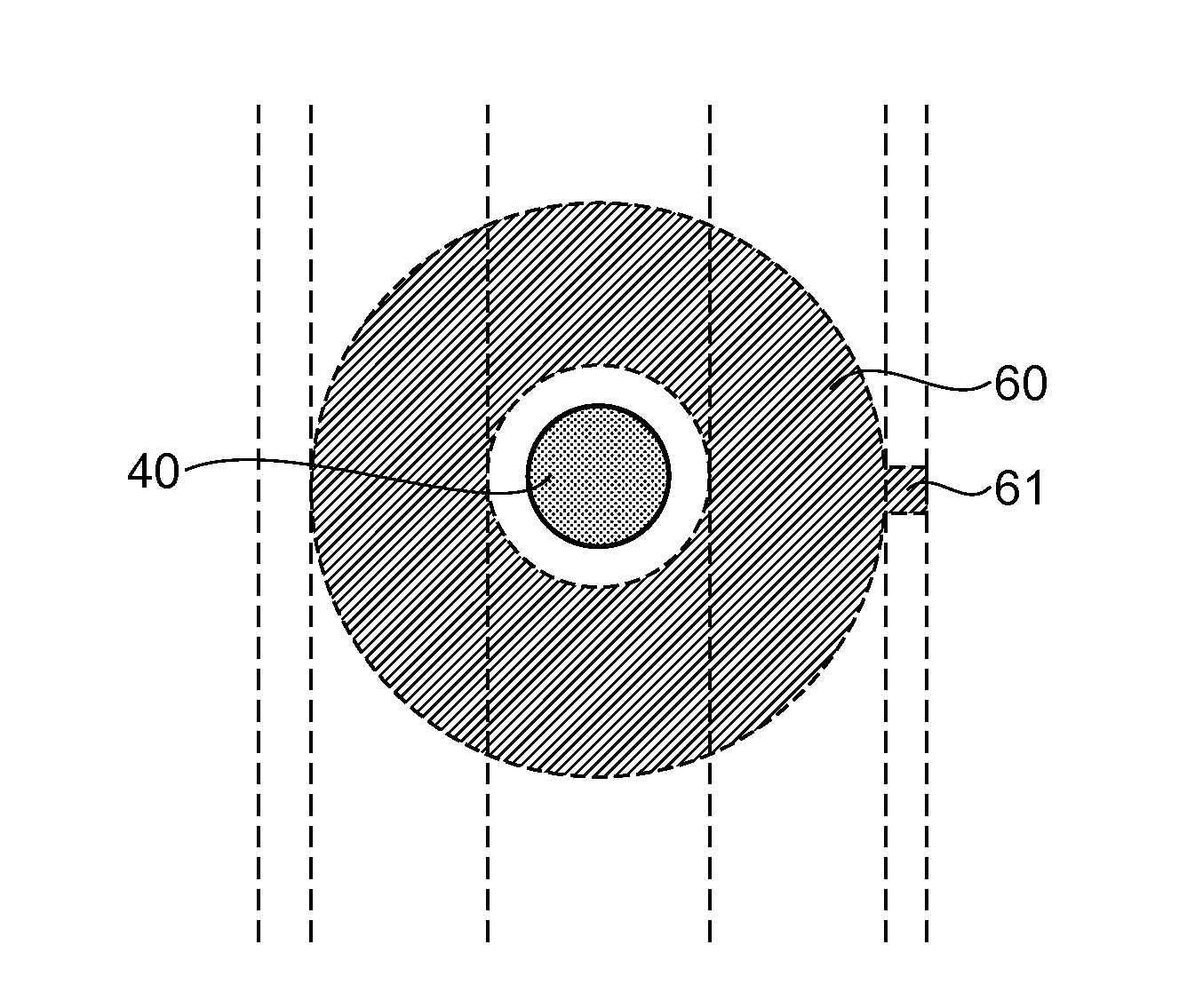
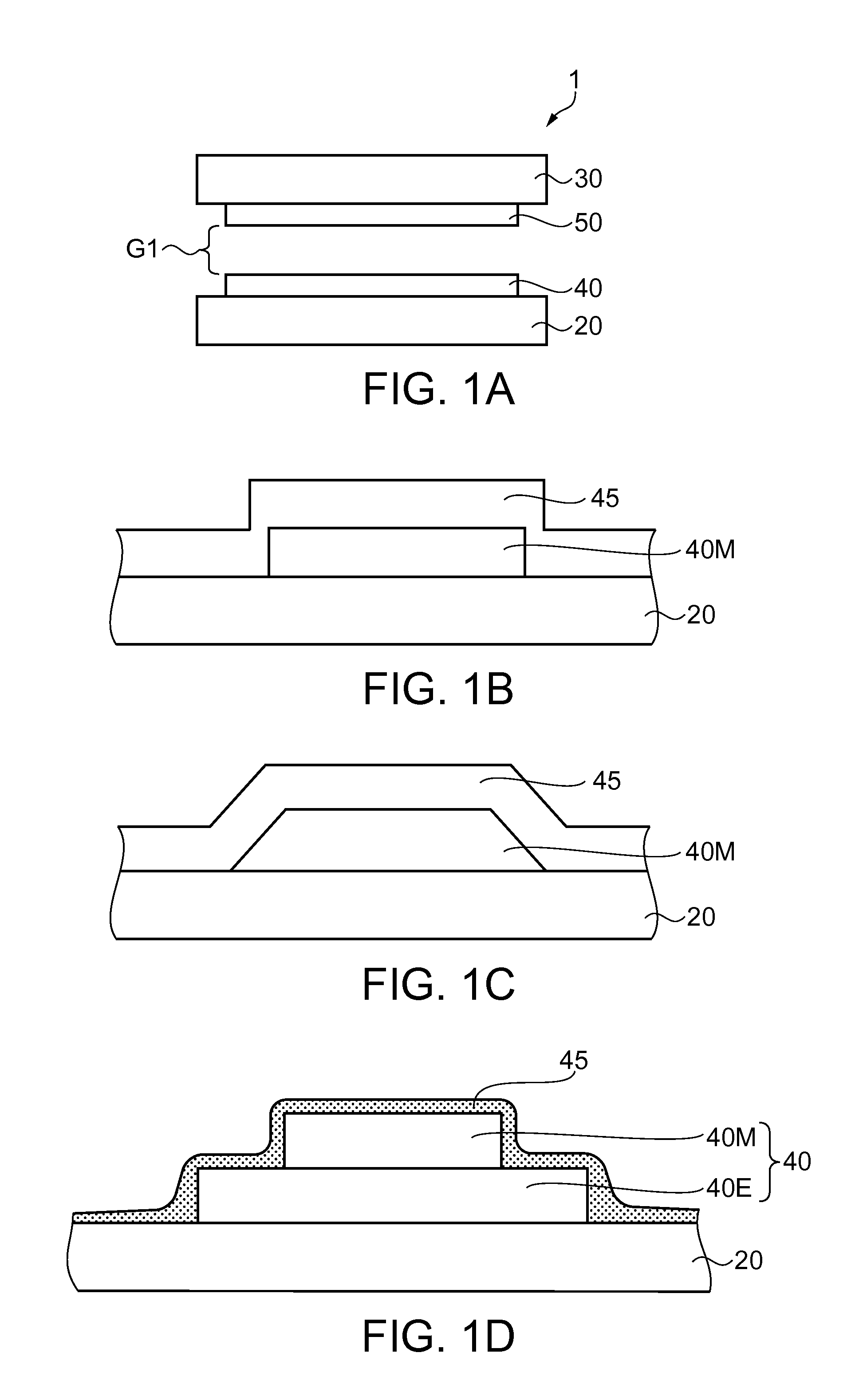
[0048]FIGS. 1A through 1D are diagrams showing an example of the structure of an optical film in an interference filter. As shown in FIG. 1A, an interference filter 1 has a first substrate 20 and a second substrate 30 held in parallel to each other, a first optical film 40 disposed on the first substrate 20, and a second optical film 50 disposed on the second substrate 30. The first substrate 20 or the second substrate 30 is, for example, a glass substrate having permeability with respect to the light in a desired wavelength band.

[0049]Further, the first optical film 40 and the second optical film 50 are formed so as to be opposed to each other and have a predetermined gap G1 therebetween. It should be noted that it is possible to make the gap G1 variable, and such a variable wavelength interference filter (hereinafter also referred to as an etalon) will be described later. The first optical film 40 and the second optical film 50 are provided with both of a reflecting property and a...

second embodiment

[0084]Then, an optical module and an electronic apparatus using the etalon explained in the first embodiment described above will be explained. In the second embodiment, a colorimetric device for measuring the chromaticity of a measurement object will be explained as an example.

[0085]FIG. 3 is a block diagram showing a configuration of the colorimetric device.

[0086]A colorimetric device 80 is provided with a light source device 82 for irradiating a test object A with the light, a colorimetric sensor 84 (an optical module), and a control device 86 for controlling an overall function of the colorimetric device 80.

[0087]The colorimetric device 80 is a device for irradiating the test object A with the light from the light source device 82, receiving the test target light reflected by the test object A using the colorimetric sensor 84, and analyzing and then measuring the chromaticity of the test target light based on a detection signal output from the colorimetric sensor 84.

[0088]The li...

third embodiment

[0102]An example of the gas detection device will hereinafter be explained with reference to the accompanying drawings.

[0103]FIG. 4 is a cross-sectional view showing an example of the gas detection device provided with the etalon.

[0104]FIG. 5 is a block diagram showing a configuration of a control system of the gas detection device.

[0105]As shown in FIG. 4, a gas detection device 100 is configured including a sensor chip 110, a channel 120 provided with a suction port 120A, a suction channel 120B, an exhaust channel 120C, and an exhaust port 120D, and a main body section 130.

[0106]The main body section 130 is composed of a detection section (an optical module) including a sensor section cover 131 having an opening to which the channel 120 is detachably attached, an exhaust section 133, a housing 134, an optical section 135, a filter 136, the etalon (the variable wavelength interference filter) 5, alight receiving element 137 (a light receiving section), and so on, a control section ...


PUM


Abstract

An interference filter includes a first substrate, a second substrate opposed to the first substrate, a first optical film provided to the first substrate, and a second optical film provided to the second substrate and opposed to the first optical film, at least one of the first and second optical films has a metal film having a reflecting property and a transmitting property with respect to light in a desired wavelength band, a surface and an edge portion of the metal film are covered by a barrier film, and the barrier film is formed of a material having conductivity.

Description

BACKGROUND[0001]1. Technical Field[0002]The present invention relates to an interference filter, an optical module, and an electronic apparatus.[0003]2. Related Art[0004]In the past, there has been known a variable wavelength interference filter as an interference filter of causing multiple interference in the light between a pair of optical reflection films to thereby emit the light with a desired wavelength (see, e.g., JP-A-2008-76749 (Document 1)).[0005]The variable wavelength interference filter described in Document 1 has substrates disposed so as to be opposed to each other, and the optical reflection films are respectively disposed on the surfaces of the respective substrates, the surfaces being opposed to each other. Further, the distance between the optical reflection films can be controlled, and it becomes possible to take out the light having the wavelength corresponding to the gap dimension between the optical reflection films from the incident light.[0006]For the optica...

Claims


Application Information

Patent Timeline
Patent Type & Authority Applications(United States)
IPC IPC(8): G02B5/28G01J1/04
CPCG02B5/284G02B26/001G01J3/51G01J1/0488G01J3/26G02B5/28
Inventor SHINTO, SUSUMU
Owner SEIKO EPSON CORP
Why Eureka
Try Eureka