Charged particle beam apparatus, and article manufacturing method

a charge-neutralizing device and particle technology, applied in the direction of photomechanical devices, instruments, heat measurement, etc., can solve the problems of affecting the efficiency of charge neutralization, the attachment of particles to the surface of the insulating body, and the residual electric potential

Inactive Publication Date: 2013-08-22
CANON KK
View PDF1 Cites 85 Cited by
  • Summary
  • Abstract
  • Description
  • Claims
  • Application Information

AI Technical Summary

Benefits of technology

[0006]The present invention provides, for example, a charge particle beam apparatus that is advantageous for neutralization of a charge of an insulator contained in a charged particle lens.

Problems solved by technology

However, when the internal portion of the lens barrel becomes during exposure to atmosphere (vent) or during evacuation, the insulating body configuring the spacer may become charged and thereby may result in a residual electric potential.
Furthermore the electrostatic component of the charge on the insulating body during exposure to atmosphere may attract and cause attachment of particles to the surface of the insulating body.
However, incorporation of the shield electrode disclosed in Japanese Patent Application Laid-Open No. 2004-55166 into the electron lens is associated with difficulties resulting from the miniaturization of the pattern to be rendered.
Furthermore, even when this type of shield electrode is provided, the charge itself is not eliminated.
The ionizer in Japanese Patent Application Laid-Open No. 2010-155367 has a disadvantage in relation to the efficiency of charge neutralization since the ions are inhibited from reaching the insulating spacer from the minute aperture of the electron lens.

Method used


Image

  • Charged particle beam apparatus, and article manufacturing method
  • Charged particle beam apparatus, and article manufacturing method
  • Charged particle beam apparatus, and article manufacturing method

Examples


first embodiment

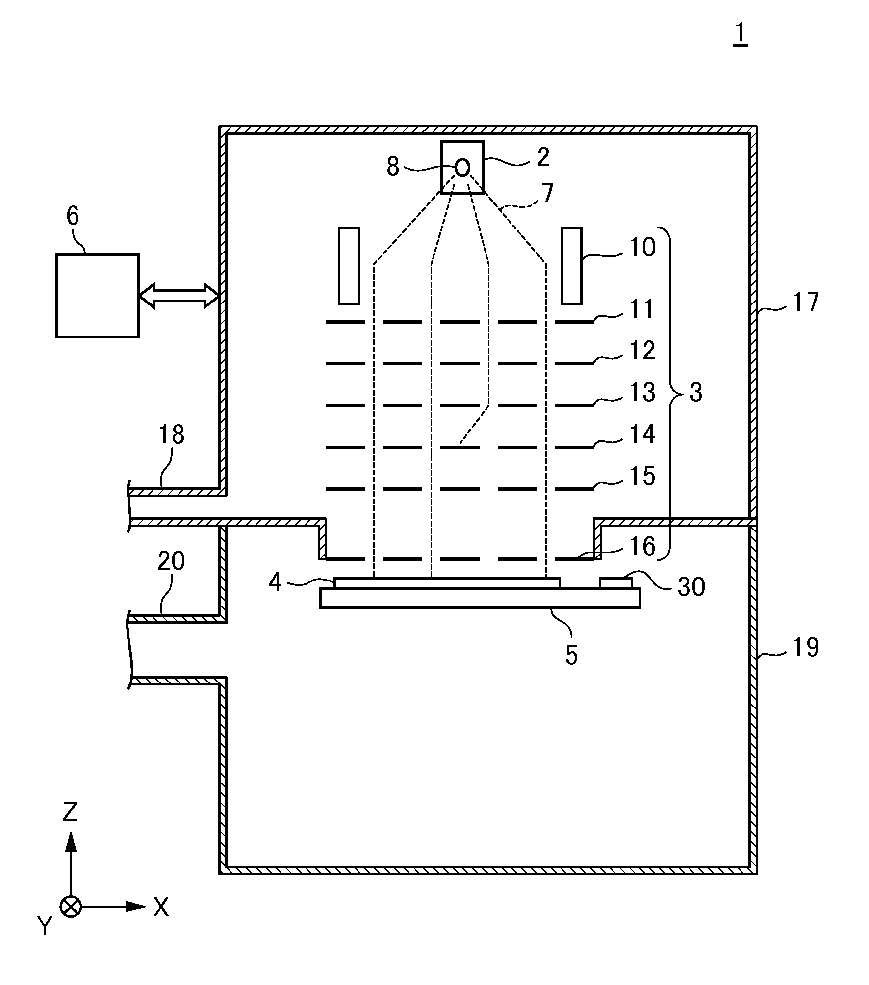
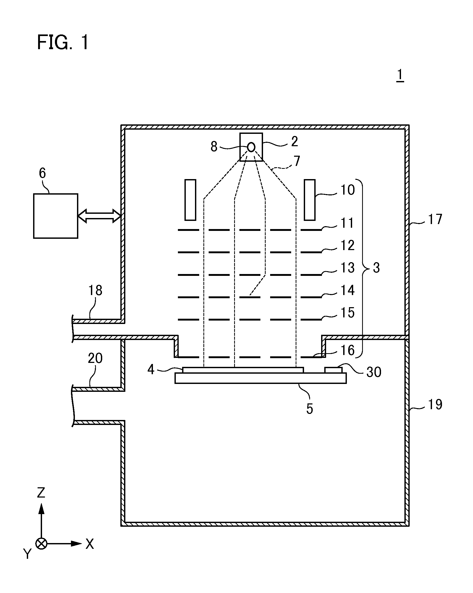
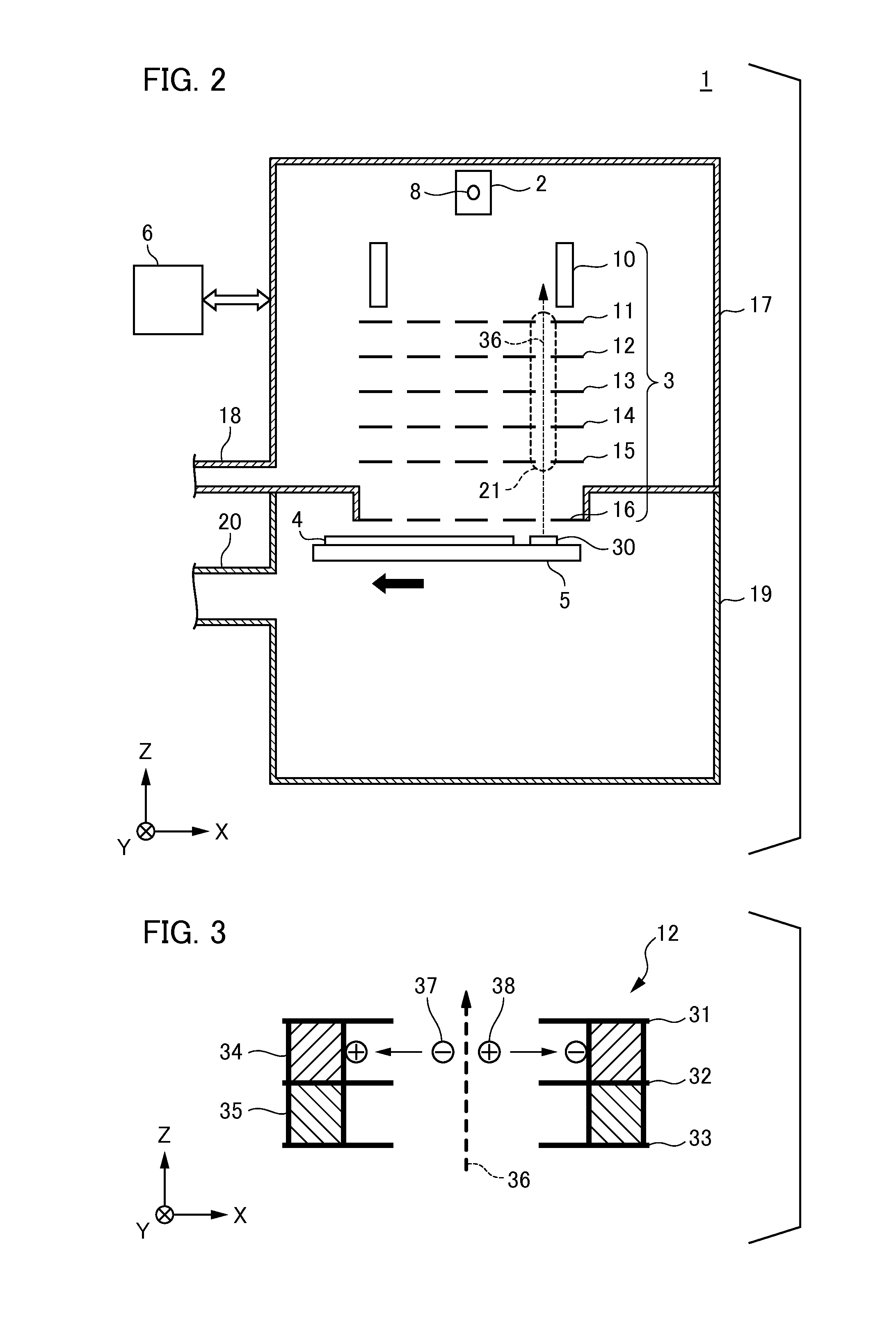
[0017]Firstly, the charged particle beam apparatus according to the first embodiment of the present invention will be described. In particular, the charged particle beam apparatus according to the present embodiment is configured as a rendering apparatus that adopts a multi method for rendering of predetermined drawing data to a predetermined location by executing deflection (scanning) of a plurality of electron beams (charge particle beams) and separate controlling the blanking (irradiation OFF) of the respective electron beams. Here, there is no limitation on the charged particle beam to the electron beam used in the present embodiment, and another configuration of a charged particle beam such as an ion line (ion beam) or the like may be used. FIG. 1 is a schematic figure illustrating the configuration of a rendering apparatus 1 according to the present embodiment. In each of the following figures, the radiation direction of the electron beam relative to the substrate (body to be ...

second embodiment

[0028]Next, the charged particle beam apparatus according to a second embodiment of the present invention will be described. The characteristic features of the charged particle beam apparatus according to this embodiment is the point that the radiation source that is equivalent to the radiation source 30 in the rendering apparatus 1 according to the first embodiment is not disposed on the surface of the substrate stage 5, but rather is disposed on an external portion of the stage chamber 19. FIG. 4 illustrates a configuration of a rendering apparatus 40 according to a second embodiment of the present invention that corresponds to the rendering apparatus 1 according to the first embodiment illustrated in FIG. 1. In FIG. 4, disclosure is omitted in relation to the feature that the substrate stage 5 displaces from the illumination region of the electron beam 7 and is placed in a refuged configuration. In this case, the stage chamber 19 includes a transmission plate (transmission portio...

third embodiment

[0030]Next, the charged particle beam apparatus according to a third embodiment of the present invention will be described. The characteristic feature of the charged particle beam apparatus according to this embodiment is the point that a radiation source that is similar to the radiation source 30 in the rendering apparatus 1 according to the first embodiment is disposed in a gate valve disposed on a partitioning portion between the collimator lens 10 and the aperture array 11 in the electron optical system barrel 17. FIG. 6 is a schematic view illustrating a configuration of a rendering apparatus 50 according to the present embodiment that corresponds to the rendering apparatus 1 according to the first embodiment illustrated in FIG. 1. Firstly, the rendering apparatus 50 includes a partition 53 that separates the internal space of the electron optical system barrel 17 into a first space 51 that includes the electron source 2 and a second space 52 that includes the electronic optica...


PUM


Abstract

A charged particle beam apparatus for processing an object using a charged particle beam includes a charged particle lens in which an array of apertures, through each of which a charged particle beam passes, is formed; a vacuum container which contains the charged particle lens; and a radiation source configured to generate an ionizing radiation; wherein the apparatus is configured to cause the radiation source to pass the ionizing radiation through the array of apertures in a state in which a pressure in the vacuum container is changing.

Description

BACKGROUND OF THE INVENTION[0001]1. Field of the Invention[0002]The present invention relates to a charged particle beam apparatus and to an article manufacturing method using the apparatus.[0003]2. Description of the Related Art[0004]A rendering apparatus (charged particle beam apparatus) is known that executes rendering on a substrate by controlling blanking and deflection / scanning of a charged particle beam such as an electron beam or the like. The rendering apparatus can be adopted in relation to one pattern formation technique in substitution for a light exposure method for the production or the like of a memory device of 4GDRAM or later that has a line width of 0.1 μm. In this type of rendering apparatus, an electrostatic lens that includes a plurality of electrode layers, and spacers formed from an insulating body that are disposed between the electrodes is used as an electron lens for focusing the electron beam. The electrostatic lens is disposed in the lens barrel that can ...

Claims


Application Information

Patent Timeline
Patent Type & Authority Applications(United States)
IPC IPC(8): H01J37/317
CPCH01J37/026H01J37/3177B82Y40/00H01J37/3174B82Y10/00H01J2237/182
Inventor TANAKA, ICHIROMIYAKE, AKIRA
Owner CANON KK
Why Eureka
Try Eureka