Optical layered body, polarizer, and image display device

a technology of optical layers and polarizers, applied in the direction of cellulosic plastic layered products, polarising elements, instruments, etc., can solve the problems of reducing productivity, marking leaves a trace of itself on the surface of hard coat layers, and achieve excellent blocking resistance, prevent curled and damaged, and prevent sticking

Active Publication Date: 2013-08-29
DAI NIPPON PRINTING CO LTD
View PDF3 Cites 16 Cited by
  • Summary
  • Abstract
  • Description
  • Claims
  • Application Information

AI Technical Summary

Benefits of technology

[0125]The optical layered body of the present invention has the above structure, and thus has excellent blocking resistance and is prevented from sticking to another optical layered body. Since the hard coat layer is a specific cured resin article, the hard coat layer is prevented from being curled and damaged, has a high pencil hardness, excellent abrasion resistance, and excellent optical properties. Also, the hard coat layer can be prevented from having trace of a marking when irradiated with UV light through a protective film having a marking so as to be processed to form a polarizer.
[0126]The optical layered body of the present invention can be particularly suitable for high definition displays such as cathode ray tube (CRT) displays, liquid crystal displays (LCD), plasma displays (PDP), electroluminescence displays (ELD), field emission displays (FED), touch panels, electronic paper, and tablet PCs.

Problems solved by technology

Because of this nature, the optical layered bodies are not easily separated from each other when rolled or subjected to another treatment in the production process, i.e., they exhibit a phenomenon called blocking.
Blocking may change the shape of the optical layered bodies or leave trace of sticking on the optical layered bodies, and thus causes a problem of a productivity decrease.
The different levels of cross-linked curing shrinkage result in a problem that the marking leaves trace of itself on the surface of the hard coat layer.

Method used


Image

  • Optical layered body, polarizer, and image display device
  • Optical layered body, polarizer, and image display device
  • Optical layered body, polarizer, and image display device

Examples


example 1

[0133]An amount of 4 parts by mass of IRGACURE 184 (product of Ciba Specialty Chemicals) was dissolved in methyl isobutyl ketone to a final solids content of 35% by mass. The solution obtained was mixed with 80 parts by mass (solids content) of PETA and 20 parts by mass (solids content) of an acrylic polymer (Tg=50° C., Mw=19,000, acid number=0.8, amount of acrylic double bonds=230, hydroxyl value in solids content=146) to a final solids content of 35% by mass, and the solution was stirred.

[0134]To the resulting solution was added 0.2 parts by mass (solids content) of a leveling agent (product name: Defensa MCF-350-5, product of DIC), and the solution was stirred. The solution was further mixed with 1 part by mass (solids content) of a lubricant (product name: SIRMIBK15WT %-E65, silica particle dispersion, product of CIK NanoTek Corporation), and the solution was stirred. Thereby, a hard coat layer composition was obtained.

[0135]The obtained hard coat layer composition was applied t...

examples 2 to 8

, COMPARATIVE EXAMPLES 1 TO 7, REFERENCE EXAMPLE 1

[0136]A hard coat layer was formed on a TAC substrate and an optical layered body was obtained in the same manner as in Example 1, except that the (meth)acrylic polymer, the solvent, the ratio (mass ratio) of the solvent, and the lubricant for the hard coat layer composition were changed as shown in Table 1. The styrene-acrylic particles shown in Table 1 were Aica Aitron 2732 from Aica Kogyo Company, Limited.

[0137]The obtained optical layered body was evaluated for the following items. Table 2 shows the evaluation results.

[0138]Two optical layered bodies were prepared for each of a large size (e.g. A4 size) and a size larger than the large size. The two bodies are sandwiched by hands such that the hard coat layers of the bodies come into contact with each other, and the bodies are strongly rubbed against each other by the palms of the hands. The lubricity of the optical layered bodies of each size was evaluated by rubbing their hard ...


PUM

PropertyMeasurementUnit
roughnessaaaaaaaaaa
roughnessaaaaaaaaaa
roughnessaaaaaaaaaa

Abstract

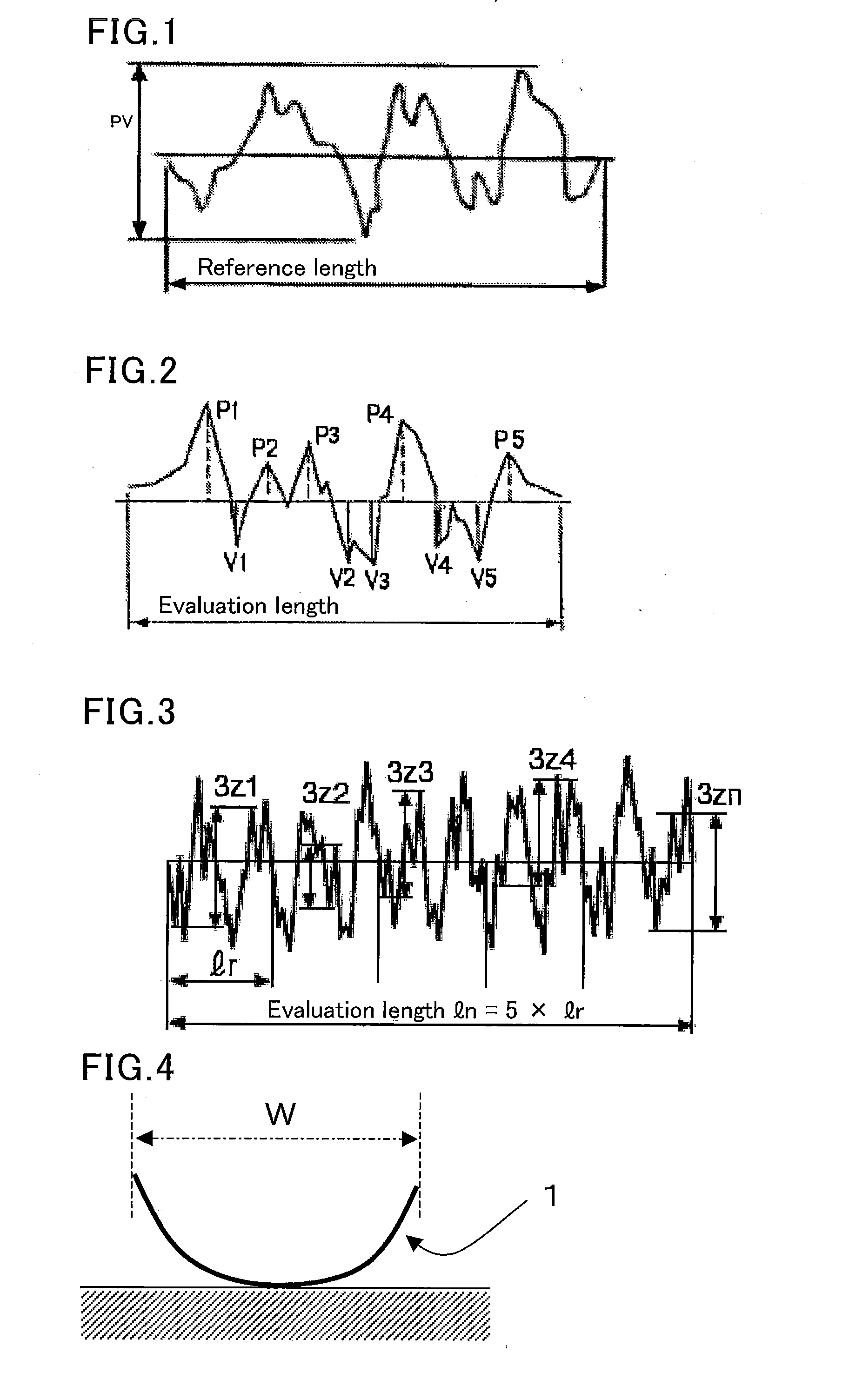
Provided is an optical layered body having excellent blocking resistance. The optical layered body includes a triacetyl cellulose substrate and a hard coat layer, the hard coat layer having fine surface roughness that has an average PV roughness Rtm of 2.2 to 11.5 nm, a base roughness depth R3z of 2.5 to 13.5 nm, and a ten-point average roughness Rz of 2.6 to 13.5 nm, and satisfy the relation Rtm<R3z≦Rz.

Description

TECHNICAL FIELD[0001]The present invention relates to an optical layered body, a polarizer, and an image display device.BACKGROUND ART[0002]Image display devices such as cathode ray tube (CRT) displays, liquid crystal displays (LCDs), plasma displays (PDPs), electroluminescence displays (ELDs), field emission displays (FEDs), touch panels, electronic paper, and tablet PCs have, on their outermost surface, an optical layered body formed from a functional layer that has various properties including an anti-glare property, an anti-reflection property, and an antistatic property.[0003]Conventionally known optical layered bodies include ones in each of which a hard coat layer is formed on a transparent substrate that is made of a material such as triacetyl cellulose. The hard coat layer is typically formed by applying a coating liquid containing polyfunctional monomers to a transparent substrate; and curing the dried coating film by UV irradiation, as described in, for example, Patent Li...

Claims


Application Information

Patent Timeline
Patent Type & Authority Applications(United States)
IPC IPC(8): G02B1/10G02B5/30
CPCG02B5/3041G02B1/10Y10T428/24355G02B1/118G02B5/30B32B7/02B32B23/04G02B5/0221G02B1/14
Inventor TSUNEKAWA, MASAYUKIYAMAMOTO, KANAIWASAKI, TOSHIKI
Owner DAI NIPPON PRINTING CO LTD
Why Eureka
Try Eureka