Electrical discharge machining

a technology of electric discharge and machining, applied in the direction of manufacturing tools, electrode supporting devices, and vibration holders of electrodes, can solve the problems of increased likelihood of short circuiting, high production cost, and large variations, and achieve the effects of improving the rate of debris removal, efficient clearing of debris, and large spark gap siz

Active Publication Date: 2013-09-26
ROLLS ROYCE PLC
View PDF27 Cites 13 Cited by
  • Summary
  • Abstract
  • Description
  • Claims
  • Application Information

AI Technical Summary

Benefits of technology

[0024]In order that the vibratory movement and fluid jets can clear the debris efficiently from the spark gap, it is typically advantageous to erode the workpiece while maintaining a larger spark gap size than is usual during conventional electrical discharge machining. For example, for a displacement velocity of the electrode of less than 1.5 mm/sec, the spark gap voltage (which is typically used as a measure of the spark gap size) may be greater tha...

Problems solved by technology

The constant motion produced by the servo motor allows for rapid drilling, but if drilling is too rapid there is an increased likelihood of short circuiting.
However, HSEDM has high production costs and can lead to large variations in typical breakthrough time to form a hole.
Also electrode wear necessitating re-working of components can be a problem.
Uneven ...

Method used


Image

  • Electrical discharge machining
  • Electrical discharge machining
  • Electrical discharge machining

Examples


Embodiment Construction

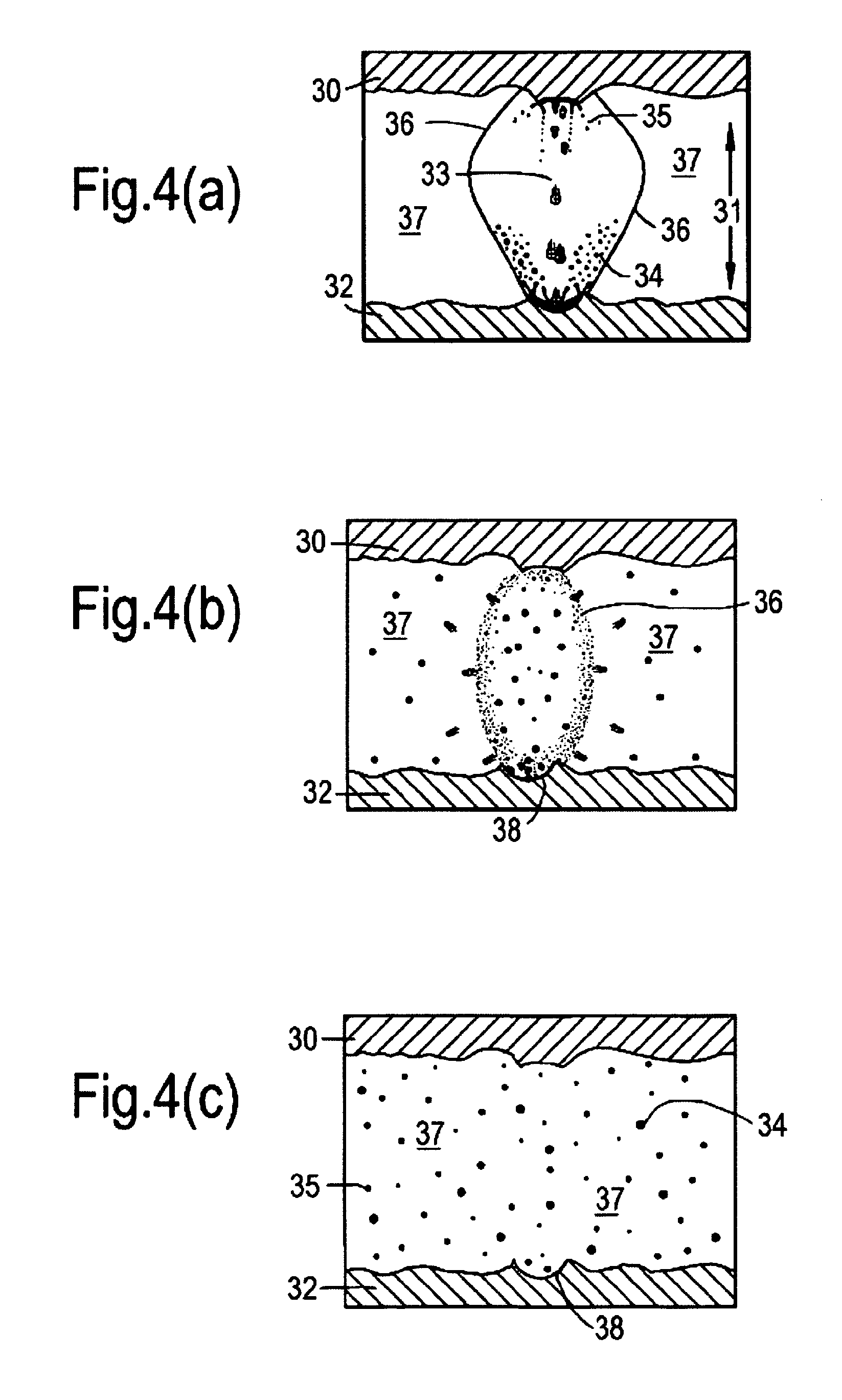
[0060]Removal of debris during HSEDM is important in order to achieve appropriate machining speeds and consistency. Debris is removed by the dielectric flushing out debris in the time between the sparks. This process is shown schematically in FIGS. 4(a) to (c). A gas bubble, illustrated in FIG. 4(a), is generated by high temperatures as a result of spark discharge. This gas bubble then implodes as illustrated in FIG. 4(b). The time between sparks, known as the “off time”, should be sufficiently long to allow dielectric fluid flushing to remove the debris. The off time determines the overall drilling cycle time for electric discharge machining. Lack of adequate debris removal therefore results in increased cycle times. Furthermore, poor debris removal increases electrode wear in the form of tapering. In FIG. 4(a), as can be seen, an electrode 30 has a spark gap 31 to a workpiece surface 32. During electrical discharge a spark-induced plasma channel 33 creates debris 34 from the workp...


PUM

PropertyMeasurementUnit
Pressureaaaaaaaaaa
Frequencyaaaaaaaaaa
Frequencyaaaaaaaaaa

Abstract

A method for electrical discharge machining a workpiece includes the steps of: presenting an elongate electrode to the workpiece with a spark gap therebetween; flowing a dielectric fluid in the gap; eroding the workpiece by electrical discharge between the tip of the electrode and the workpiece; displacing the electrode in a direction aligned with the long axis of the electrode to maintain the gap as the electrode wears and the workpiece is eroded; and simultaneously with the displacement, producing vibratory movement of the electrode, the vibratory movement being aligned with the long axis of the electrode.

Description

FIELD OF THE INVENTION[0001]The present invention relates to electrical discharge machining (EDM) and more particularly, but not exclusively, to so-called high speed electrical discharge machining (HSEDM) utilised for forming holes in components such as blades for gas turbine engines.BACKGROUND OF THE INVENTION[0002]EDM is utilised with regard to processing of workpieces by spark erosion. The workpiece and the electrode (usually made from graphite, copper or brass) are generally presented with a dielectric fluid between them and are connected to a DC power supply (EDM generator) delivering periodic pulses of electric energy, such that sparks erode the workpiece by melting and vaporisation and so create a cavity or hole or otherwise shape a workpiece. In order to provide for spark erosion, the workpiece and the electrode must have no physical contact and a gap is maintained typically through appropriate sensors and servo motor control. Erosion debris must be removed from the erosion ...

Claims


Application Information

Patent Timeline
IPC IPC(8): B23H1/08B23H7/30
CPCB23H1/10B23H7/26B23H1/08B23H7/38B23H7/30B23H1/00B23H9/14B23H11/00B23H11/003
Inventor LEAO, FABIO NOGUEIRAXIDACIS, ALEXANDERCUTTELL, MARTYN
Owner ROLLS ROYCE PLC
Why Eureka
Try Eureka