Multi charged particle beam writing apparatus and multi charged particle beam writing method

a writing apparatus and charged particle technology, applied in the field of multi-charged particle beam writing apparatus and multi-charged particle beam writing method, can solve the problems of reducing the operation rate of the writing apparatus, reducing the writing throughput, and several days

Active Publication Date: 2013-09-26
NUFLARE TECH INC
View PDF3 Cites 31 Cited by
  • Summary
  • Abstract
  • Description
  • Claims
  • Application Information

AI Technical Summary

Problems solved by technology

However, since many beams in a large area are used in the multi-beam system, it is difficult to make each current uniform.
However, unlike the single beam system, since a large number of beams are used in the multi-beam system, it may take several days to measure all of the current value of each beam by using the Faraday cup on the stage.
Therefore, the writing processing is stopped during the m

Method used


Image

  • Multi charged particle beam writing apparatus and multi charged particle beam writing method
  • Multi charged particle beam writing apparatus and multi charged particle beam writing method
  • Multi charged particle beam writing apparatus and multi charged particle beam writing method

Examples


embodiment 1

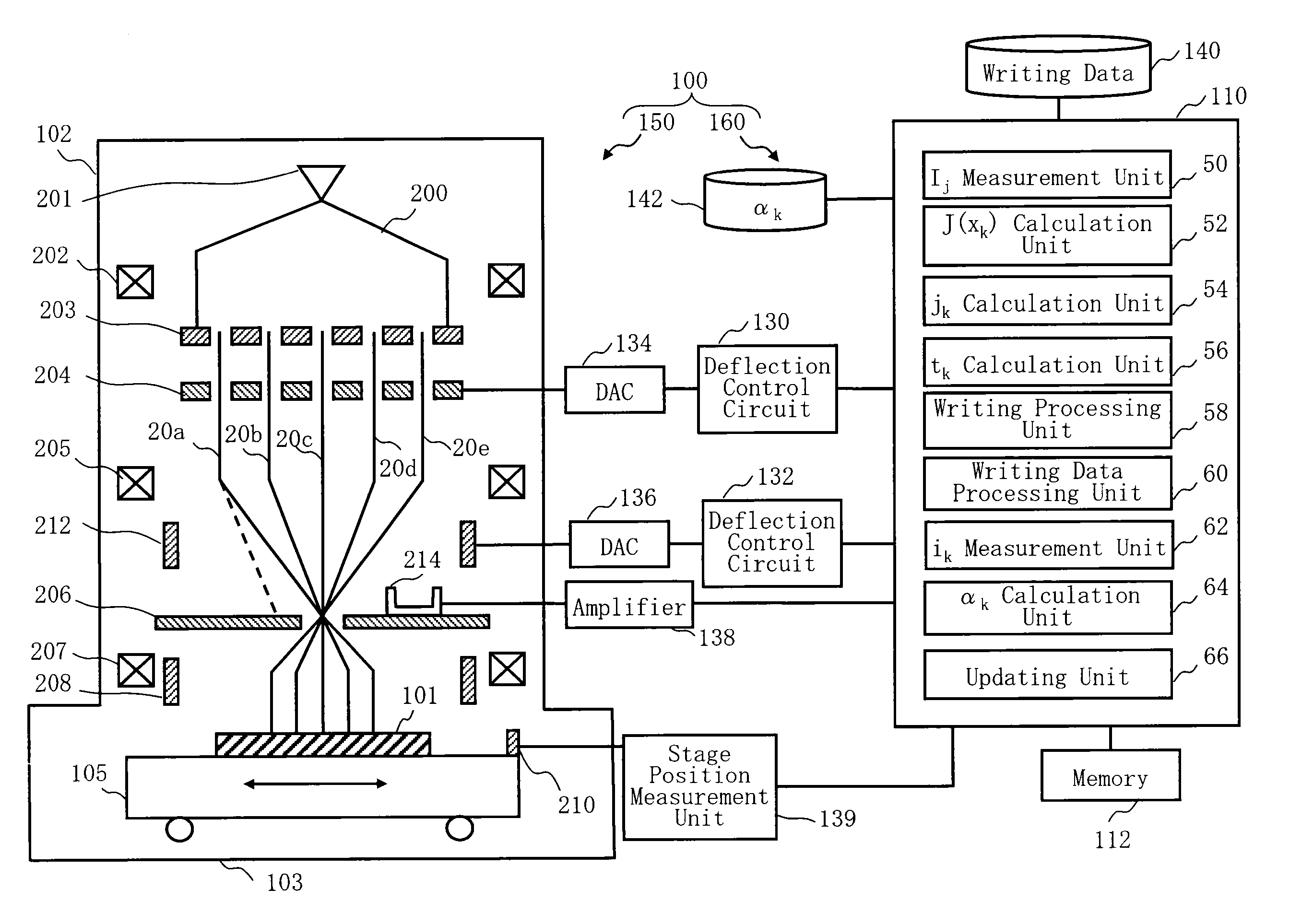
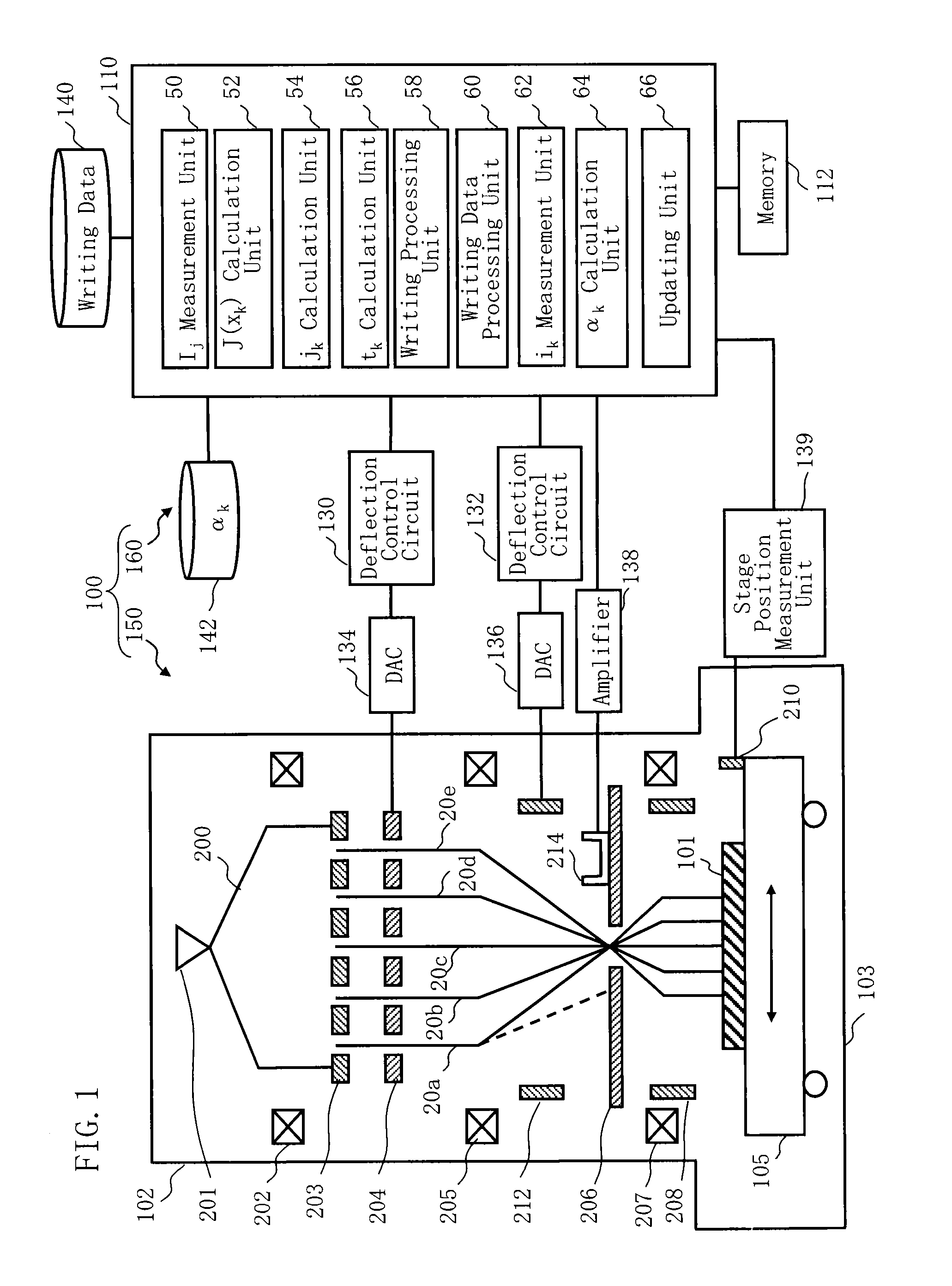
[0025]FIG. 1 is a schematic diagram showing a configuration of a writing apparatus according to Embodiment 1. In FIG. 1, a writing (or “drawing”) apparatus 100 includes a writing unit 150 and a control unit 160. The writing apparatus 100 is an example of a multi charged particle beam writing apparatus. The writing unit 150 includes an electron lens barrel 102 and a writing chamber 103. In the electron lens barrel 102, there are arranged an electron gun assembly 201, an illumination lens 202, an aperture member 203, a blanking plate 204, a reducing lens 205, a deflector 212, a limiting aperture member 206, an objective lens 207, and a deflector 208. In the writing chamber 103, there is arranged an XY stage 105, on which a target object or “sample”101 such as a mask serving as a writing target substrate is placed. The target object 101 is, for example, an exposure mask used for manufacturing semiconductor devices, or a semiconductor substrate (silicon wafer) on which semiconductor ele...


PUM


Abstract

A multi charged particle beam writing apparatus includes a unit to calculate a predetermined function expression by a correction coefficient that corrects an open area of each opening for forming a beam group, wherein the predetermined function expression minimizes a sum of squared values of all the beam groups, where each of the squared values is calculated by squaring a difference between a current value measured of the beam group and a sum of products for the beam group, where each of the products is obtained by multiplying a corrected open area by the predetermined function expression; a unit to calculate the correction coefficient that corrects the open area by using the predetermined function expression and the current value of the beam, for each beam; and a unit to calculate a current density of each of the multiple beams by the predetermined function expression.

Description

CROSS-REFERENCE TO RELATED APPLICATION[0001]This application is based upon and claims the benefit of priority from the prior Japanese Patent Application No. 2012-065387 filed on Mar. 22, 2012 in Japan, the entire contents of which are incorporated herein by reference.BACKGROUND OF THE INVENTION[0002]1. Field of the Invention[0003]The present invention relates to a multi charged particle beam writing apparatus and a multi charged particle beam writing method. For example, the present invention relates to a method of obtaining high accuracy of multi-beam writing.[0004]2. Description of Related Art[0005]The lithography technique that advances microminiaturization of semiconductor devices is extremely important as being a unique process whereby patterns are formed in the semiconductor manufacturing. In recent years, with high integration of LSI, the line width (critical dimension) required for semiconductor device circuits is decreasing year by year. The electron beam (EB) writing techn...

Claims


Application Information

Patent Timeline
IPC IPC(8): H01L21/02
CPCH01L21/02675G03F7/2059H01J37/3177B82Y40/00H01J2237/30455H01J2237/31794B82Y10/00H01J2237/30433
Inventor MATSUMOTO, HIROSHI
Owner NUFLARE TECH INC
Why Eureka
Try Eureka